
Plan Session
Plan session
Note: Remote-use clients cannot use Plan Session to alter the session plan established by the Therapist unless enabled by the Therapist. Changes made here are ignored when a session is started unless enabled.
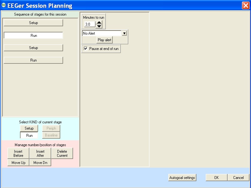
Every session requires a "session plan". This is the time/place that initial site locations, frequencies, feedback modes, and autogoal selections are made. Most of these selections are changeable during a session but an initial plan is required. There is a separate session plan for each layout. A session plan is comprised of a number of "stages". Each stage is a particular action/operation such as electrode placement, providing feedback, etc. In this version of EEGer, there are two kinds of "stages": Setup stages (electrode placement, frequency/mode establishment) and Run stages (actual feedback for a planned time). A plan is saved for each client/protocol class/layout combination (Each client has a session plan for each protocol class created using the Create client class option). Clicking on the Plan Session button brings up the following screen:
This display has three "panes". The leftmost pane is where stages are created or selected. At the top of the left pane is a series of buttons showing which "stage" of a session is being modified. Clicking these buttons "selects" that stage for modification (and changes the display shown in the center and right panes). The bottom of the left pane has buttons allowing for creating and deleting stages or changing what kind of stage it is to be. In the center pane are the values for the currently selected stage. On the right pane (for Setup stages) is a symbolic head with electrode placements and a graph showing the frequency bands for the current filter frequency settings.
Clicking on the
Insert Before or Insert After button adds a new stage with a type of "Empty".
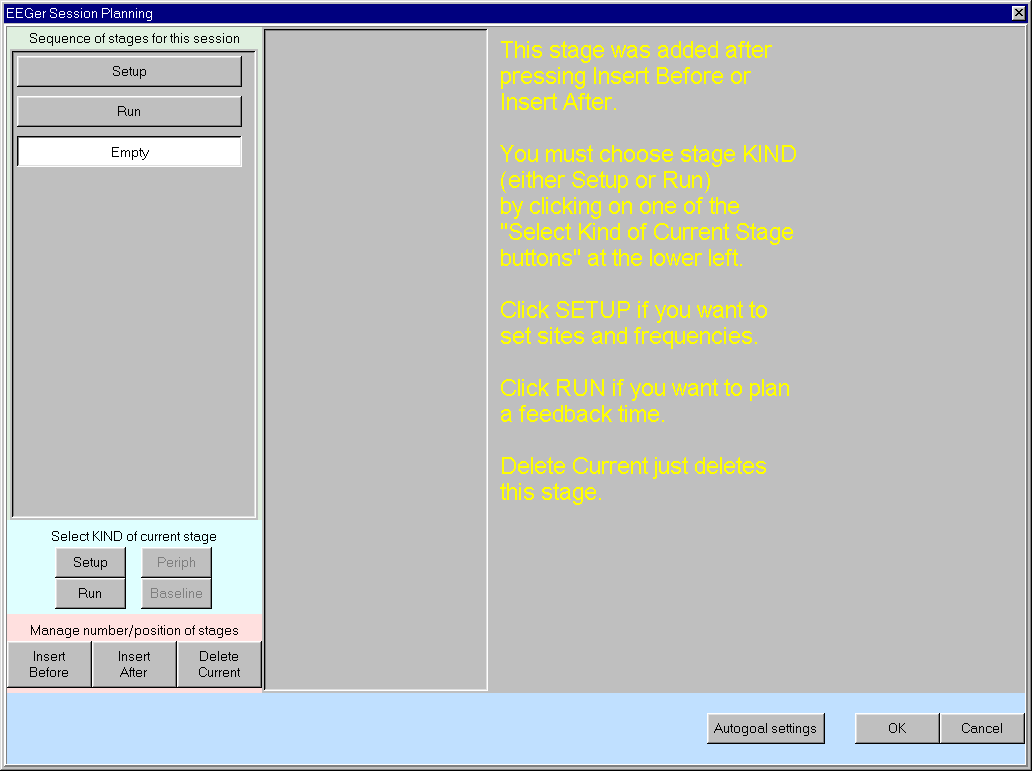
The Empty stage type must be set to a valid type by clicking on either Run or Setup. The Delete Current button deletes a stage (in this case bringing us back to the original screen).
To change the site locations, you must click in one of the channels. You can then type in values or use the mouse to click on desired locations (or the Clear box to reset channel values). Clicking on the blue box labeled 10-10 (or 10-20) toggles between the 10-20 placement diagram and the 10-10 (modified) placement diagram.
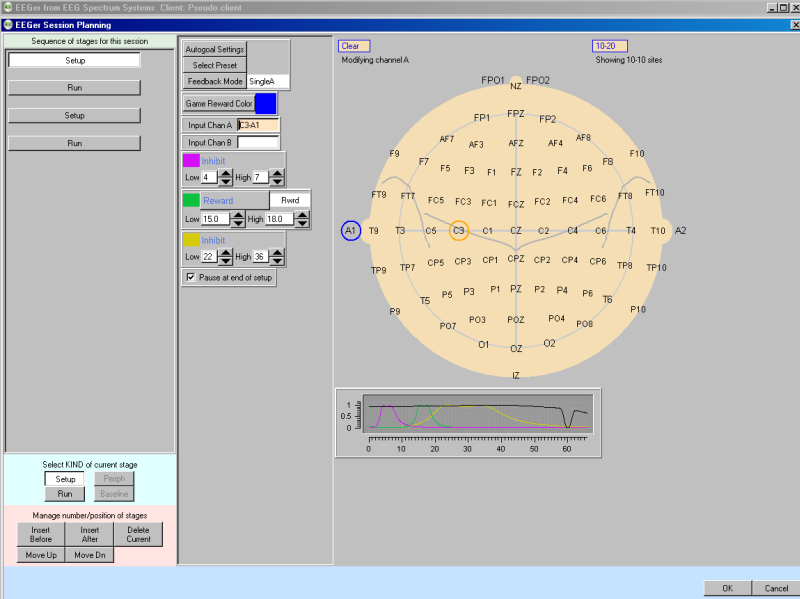
Clicking on the Feedback Mode button (top center) pops up a menu of choices for (starting) feedback modes showing all the possibilities. It is possible to select a mode at the planning stage (now) that there is no license for. At actual feedback time, any unlicensed condition will cause SingleA (single channel, A input) to be selected. Of course, you can change the feedback mode (using F3) during the actual feedback process.
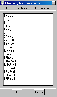
The modes work as follows:
SingleA- Single channel, source data from the "A" input channel
SingleB- Single channel, source data from the "B" input channel
Sum - Sum of A and B channels is used as source data
Differ - Difference of A and B channels is used as source data
Psync- Comparison between filtered A and B envelopes (formerly Synchrony)
Async- Comparison between filtered A and B envelope slopes (formerly Comodulation)
GAsync- Comparison between lowpass A and B envelope slopes (formerly Global Comodulation)
AminusB- Difference between filtered A and B envelopes
BminusA- Difference between filtered B and A envelopes
PDelta- Phase difference between A and B signals
RatioA- Ratio of reward to inhibit (A as source)
RatioB- Ratio of reward to inhibit (B as source)
RatioAB- Ratio of A channel reward band amplitude to B channel reward band amplitude.
RatioBA- Ratio of B channel reward band amplitude to A channel reward band amplitude.
D/S-Ratio- Ratio of (A-B) to (A+B)
D/S-Ratio- Compute 1-|(A-B)|/(A+B) similar to D/S-Ratio except absoulte value.
The remaining choices are only available if the ZSCORE module is installed. See the ZSCORE appendix for information about these modes.
Clicking on the Presets button (top center) brings up a selection list of defined presets. These are the values set (changed) from the user-defined presets established as preferences using the Preferences menu (Edit filter setups).
.
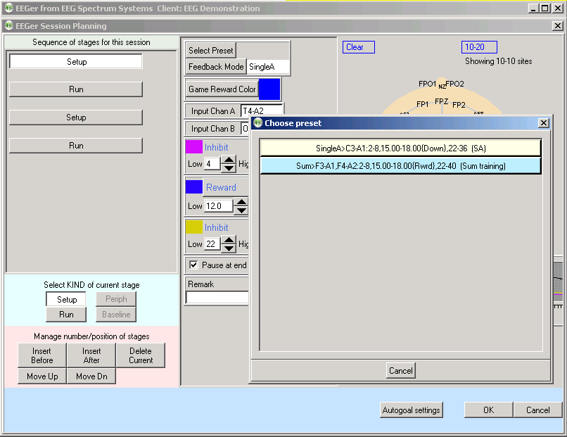
Selection of one of the presets from the list causes the preset-stored filter and site values to replace the current setup stage values.
Clicking on a Run stage button brings up a slightly different screen. Notice there is no "head" shown. The important field on this screen is the run time (Minutes to run).
Clicking on Autogoal settings at the bottom of the session planning screen brings up a menu which allows adjustment of threshold values used when F11 is pressed (Alpha-Theta example shown).
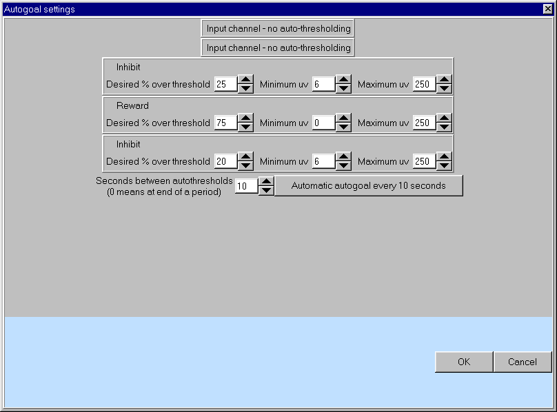
Any stream with 0 % selected will have NO change made when F11 is pressed. The Minimum uv value is the minimum (measured average value) threshold that will ever be "automatically" set by F11. The Maximum uv value is the largest threshold value that will be set by F11. The Autogoal only on F11 button is a toggle where the other value is Automatic autogoal every rest period or Automatic autogoal every xx seconds where xx is the number of seconds in the entry box. Clicking on OK saves the autogoal settings and returns to the session planning screen. When the F2 key is used during real-time processing to switch between up and down rewarding, the appropriate percentages would be reversed (i.e. 65% would become 35%).
On the session planning screen, clicking on the OK button saves the session plan and returns to the top menu. You cannot click on OK if any field is highlighted with a pink background (marking it as in error).