Brainwave screen
The brainwave screen looks like this:
There is a lot of information on this screen. Generally speaking, the upper part of the screen contains signal data and the lower part contains process/progress data.
There are several popup menus which can be used to control autogoal thresholds, volume, tactile feedback settings, etc. The menus work alike in that the line to alter is controlled by PageUp/PageDown and the settings change by the "+" and "-" keys (just like threshold settings).
The Esc key closes any popup screens and continues processing. If no popups, it terminates realtime processing (without warning) and returns to the top menu.
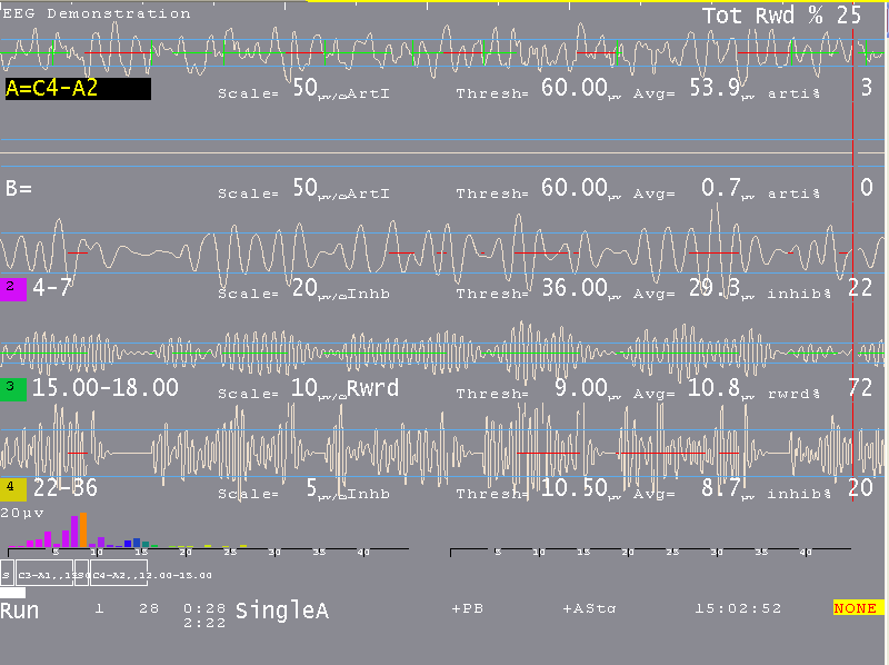
This sample shows a typical single channel setup. The top two streams are the input channels (labeled "
A" and "B"). The "A" channel electrodes are at C4-A2.
The three streams below that are reward and inhibit streams (labeled at about the middle of each stream display). Possible legends are:
1. ArtI Artifact Inhibit (lowpass data)
2. Inhb Inhibit
3. Rwrd Reward (signal above threshold
4. Down Reward (signal below threshold)
5. Monitor
(Additionally, for advanced users:)
1. Cntr Reward (signal close to threshold)
2. Elev Reward (signal above threshold, clamp to threshold)
3. DevU Reward (deviation above)
4. DevD Reward (deviation down)
5. Band Reward (signal between band limits set by Band Control popup.
The current frequency range of each stream is shown at the left near the colored blocks. The "color" of the blocks is based on the center frequency of the frequency range (using the customizable colors previously mentioned in the Tools menu description). The Scale, Thresh, and Avg values are in microvolts (peak-to-peak). The inhib% value is the percent of time the signal was over the threshold voltage (for inhibits). The rwrd% is the time in reward state (for rewards) (smoothed over the previous 30 seconds). The Avg value is the average value of the signal smoothed over the previous 30 seconds. The blue horizontal lines represent the relative position of the threshold setting. The Tot Rew % value in the upper right corner is the (smoothed over 30 seconds) percent of time the client is in overall reward state (no inhibits/artifacts and in reward state).
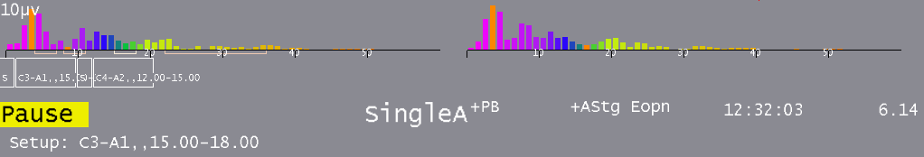
The (frequency) colored bars at the bottom are a measure of the energy contained in each 1 Hertz frequency range from 0 to 45 Hz. They are computed as FFT (Fast Fourier Transform) values every �; second. If the FFT Highlight mode is on (toggled by Alt-F10), the highest/lowest FFT amplitudes between 1 and 20 Hz will be color-coded with colors 49/50 of the current color set. This is a method of seeing where dominant values lie every �; second. The FFT scale maximum value is shown in microvolts on the left of the FFT area.
A typical two-channel screen might look like this:
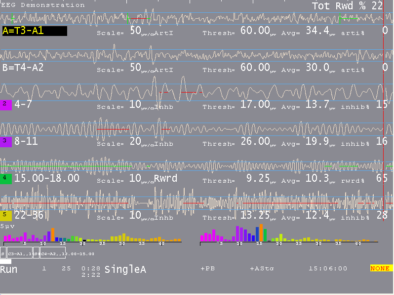
Several other features are shown on this screen. The reward stream shows a GREEN line in the center meaning signal-in-reward-condition. The high frequency band below it has a RED line meaning signal-above-threshold. Red lines inhibit rewards while green lines permit rewards (if there are no inhibits). The red lines in the input streams are times when an artifact (signal over threshold) has been detected/processed. The horizontal green lines are times when all reward criteria have been met (no artifacts/inhibits and all rewards ok). The vertical green lines reaching from threshold line to threshold line indicate a reward/"score" has been issued.
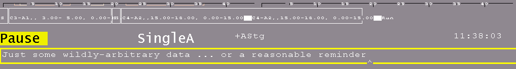
The bottom area of the screen has a number of regions of data. Shown below are some boxes with text inside. This is a graphical representation of the session plan. The little boxes with "S" inside represent Setup stages. The run stages have the setup text from the previous setup and a width proportional to the specified run time. The entire bottom width is scaled to represent the maximum session time (from the preferences screen). The white progress bar is filled in to show the current position in the session plan. The boxes, text, and bar disappear if the session plan is no longer being followed.
Below the boxes is a line of status information. The leftmost field contains the current status of feedback (Pause, Run, Rest, Stage,Wait) with a different background color for each status. "Pause" is shown when an operator action (F5) is required to continue the session. "Rest" status is shown during the rest periods between periods and implies no operator action is required. "Stage" is shown when there is an operator action/decision needed (move electrodes, continue/change session process, etc.). "Wait" is shown while waiting for the game to respond to its initialization.
The current period, score, and feedback time (minutes:seconds) is shown to the right of the current status. Below the feedback time is shown the time remaining before a status change takes place (like Run to Rest or Rest to Run). Next is shown the current feedback mode (SingleA).
There are a number of flags and operator-changeable modes whose state is shown in the middle of this line. Possibilities are:
+PB playback mode (not live)
+Gen signal generator mode
+Athr autothreshold (auto F11) at beginning of rest period
+Astg auto stage processing enabled
-DC DC compensation turned off
-Ainh artifact inhibit turned off
-lpf lowpass filter disabled
-Nuse unused raw trace data is suppressed
Eopn means eyes-open status
Ecls means eyes-closed status
Further right the current time-of-day is shown. At the right edge the ProComp voltage is shown (or
NONE if no ProComp is being sensed). If another I/O device is used, other data may show here. In all cases, a flashing RED message indicates a fatal error condition.
The bottom two lines contain program messages, in this case displaying the setup-specified site locations. Additionally, some generic messages may be shown about the feedback process.
Among them are:
NOT RUNNING
- EEGer paused after first run
REWARDS BLOCKED
- No more rewards are sent to game.
This is usually caused by manually exiting a game during feedback.
NOT RECORDING
- Session has run more than 90 minutes.
Feedback can continue but no more data recording will occur.
INPUT FAILURE
- Live input lost (amplifier failure or dongle removed)
KEYBOARD Lost
- EEGer is not the focus for keyboard inputs.
If this occurs, move the mouse to the brainwave screen and left-click.
RAW % too high
- Raw data so exceeds the artifact threshold that EEGer cannot adjust.
Adust raw threshold until 0%, then readjust as needed.
Pressing Shift-F8 causes the two bottom lines to be used as a single-line entry area as shown below.
F8 raises/lowers the editor screen which can be used while feedback is ongoing.