Appendix 16: Signal Problems with ProComp Systems
This sheet is designed to help resolve signal problems where the system is functioning and you are getting a signal (indicated by the battery voltage value displayed in the lower-right corner of the screen) but the signal you are getting does not look right.
Examples of a bad signal include getting large rhythmic patterns in the raw EEG, or the high frequency looks much too high, or the raw EEG doesn't seem to stay centered within the blue lines, or "this person's EEG just doesn't look like it used to". If one of these cases resembles your situation, then this sheet should help.
NOTE: If you are having a problem with the lower traces going flat and the raw EEG looks okay, it is not a signal problem. Explanation: Whenever the raw EEG stretches outside of the blue inhibit lines, because of artifact such as movement, the lower traces automatically shut off.
The purpose of this sheet is to rule out possible causes of such signal problems one at a time. In order to do this, follow the steps below, making only one change at a time, and observing the result. Continue following the steps until your problem is resolved.
PREP INSTRUCTIONS - Prep the skin by vigorously scrubbing each site, including the ears, with alcohol or Nu-Prep. Rub a small amount of electrode paste on each site, then put a dollop of paste on each electrode, and then place the electrode on the prepped site.
For this testing procedure you can be your own control. Try placing the electrode right below the hairline on your own forehead, near FP1, with reference and ground on each ear. This is not with the intention to train at this location, but to be sure that you are getting a good clean connection with no interference from hair. This method will tend to give a good contact a higher percentage of the time, and should be used in combination with the following tests in order to rule out contact as the problem factor.
Use an Impedance Meter, if available. For UFI Checktrodes sold by NeuroCybernetics, the digital number displayed should be under 20, ideally under 10. The LED light should be yellow or green, which indicates impedance is under 20 KW.
While you are testing, make sure to minimize body contact with the wiring between the electrodes and the computer. Do not have the client hold any portion of the wiring such as the preamp or ProComp. And, if possible, try to have the electrodes lie over the back of the chair, or over clothing, minimizing contact with skin other than the electrode contacts themselves which are in contact with the scalp. If you are hooking up another person, after connecting that person, step back from the system so that only the client is in physical contact with the system (another body touching the system or wiring that does not have a grounding electrode can act as an antenna and feed interference into the system). Other sources of interference include:
- Turn off any fluorescent or halogen lights in the vicinity of your system. Repeat step 1.
- Check for any electric motors or other radiating devices in close proximity such as cell phones or microwave ovens, and make sure they are turned off.
- Find out if your office is close to a radio or television station transmitter.
Swap the electrodes with a brand new set of electrodes or a set from a system that you know works. Make sure to swap the full set; don't just change out one electrode or two. (Hint: It is helpful to label the electrodes so you can tell them apart if one set does not work properly.)
Another way to test the electrodes is to touch all three ends together; the trace should go flat. If the trace does not go completely flat when all three electrodes are touching, then you have wiring problem, and could be a problem with the electrodes, the DIN cable, or the pre-amplifier (FlexPro).
Note: Electrodes are easily damaged. Therefore, don't assume that just because an electrode is rather new that it is guaranteed to be good. An electrode could even have a manufacturers defect or could be damaged in shipping. Therefore, if you have the option, it is nice to trade electrodes from a system that you know works, and/or try your brand new set on more than one system.
Change paste, use different paste, or just a new tub or tube of paste. Then completely repeat step 1. Paste can be damaged by getting it too hot or too cold.
Change the batteries in your ProComp with a brand new fresh set right out of the package. For the purposes of testing, set your rechargeable batteries aside and use a new set of regular alkaline batteries from the store.
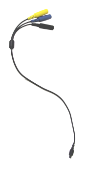
Swap the DIN cable. The din cable is the splitter that the electrodes plug into. It is the next piece after the electrodes as we move from the client toward the computer. If you do not have an extra DIN cable, call EEG Spectrum Systems to order one. Check the signal by following the procedure in step 1.
(ProComp2 models use a FlexPro pre-amplifier in Channel B, but a pre-amplifier is built into Channel A).
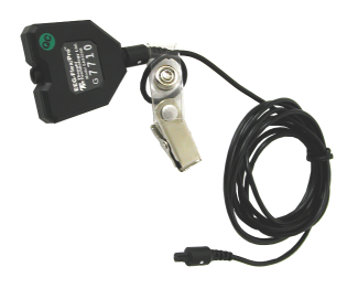
Swap the pre-amplifier (FlexPro) cable that plugs directly into the ProComp, between the ProComp and the DIN adapter cable. It has a small, five-sided black connector on one end. Check the signal by following the procedure in step 1.
A common result from a bad preamp is a square EEG on the screen. If the EEG on the screen looks square, or just looks like vertical lines all the way to the top of the screen, then try switching out the pre-amplifier. Also try holding the FlexPro in your hand and see if that affects the problem. If your FlexPro is the problem, then it can be sent in for repair.
This is the light gray, stiff wire running between the ProComp and the ProSB (square, gray fiber optic converter).
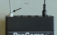
Make sure the fiber optic cable is fully inserted at both ends (insert about ˝ inch; the cable often "catches" at Ľ inch). Or replace the fiber optic cable completely. Check the signal by following the procedure in step 1. A fiber optic problem will often appear as short breaks of flat line in the RAW EEG (only the raw EEG is relevant here).
NeuroComp/DOS: On the main menu of the therapist computer, under the "Utilities" menu choose "Test system features", then choose "ProComp Test".
EEGer: Prior to 4.1.3: Download the ProComp Test from the EEGer website - <http://www.eeger.com/>.
Double-click the downloaded file to launch the program.
4.1.3 and later: Select the IOtest from the EEGer menu.
This should display a screen with two yellow bars. The top yellow bar should display a signal coming from channel A of the ProComp. Below the yellow bars you will see a set of numbers. The numbers on the left should be moving rapidly, the numbers on the right should be still. The numbers on the right may not be zeros but they should not be moving at all. If things look different from this, then you may have a problem with your fiber cable, your ProSB, or the ProComp itself. You can adjust the fiber cable while the screen is up and see if any change occurs.
Also, check the ProComp protocol setting switches by looking inside the battery compartment of the ProComp+ or ProComp2 or near the battery compartment on the outside of the ProComp Infiniti. There you will see 4 white switches. These should be set |ON|OFF|OFF|OFF| for Spectrum mode or |OFF|ON|OFF|OFF| for Biograph mode (EEGer option only).