Appendix 26: Using Checktrodeź
1. Prep the placement sites and attach the YELLOW (signal), BLUE/GREEN (reference), and BLACK (ground) electrodes. (To prep sites: Scrub the skin with a cotton swab and NuPrep. Apply the 10/20 paste directly to the electrodes.)
2. To begin testing, plug the end of the YELLOW (signal) electrode into one of the red or black holes at the bottom or side of the Checktrode. Plug the end of the BLACK (ground) electrode into the remaining hole.
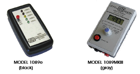
3. If you have the Model 1089III with the Digital/LCD screen display, make sure your blue dial is set to contact K? (second line from the left).
4. Press the red button on the Checktrode to test impedance.
The digital number displayed should be under 20, ideally under 10. You may go as high as 30 as long as the signal is clearly visible in the software.
If there's a "1" all the way to the left of the LCD display, this means either:
only one electrode is connected to the Checktrode OR
you need to improve the contact.
If this is the case, prep the placement site again and make sure you don't have hair under the electrode. After trying several times, it is advisable to clean up and start again; too much paste over too large an area can make it hard to get an optimal reading.
The LED light should be yellow or green, which indicates impedance is under 20K=.
If the reading is >40K=, this means either:
only one electrode is connected to the Checktrode OR
you need to improve the contact.
If this is the case, prep the placement site again and make sure you don't have hair under the electrode. After trying several times, it is advisable to clean up and start again; too much paste over too large an area can make it hard to get an optimal reading.
5. Remove the YELLOW electrode from the Checktrode and replace it with the BLUE/GREEN (reference) electrode. Repeat Step 4 with the BLUE and BLACK electrodes connected to the Checktrode.