EEGer4™
Neurofeedback
Software
Technical Manual
Version 4.4.0
This manual
contains information intended for licensees of EEGer software.
All information is
Copyright © 2011-2021 EEG Software and all rights are reserved by
EEG Software.
Initial release 31 July 2012
TM43001 16 August
2012 for standardized revision control
TM43002 09
December 2012 to add data acquisition methodology
TM43003 30 January
2013 for added explanation of amplifier test/data
TM44001 1 November
2017
TM44002 01 June
2021
Computer Requirements
EEGer software requires one or two computers to operate
(depending upon user configuration selections). EEGer executes on
the following operating system configurations:
-
Windows 7 32-bit
-
Windows 7 64-bit
-
Windows 8
-
Windows 8.1
-
Windows 10
The most sensitive element in a computer system (for EEGer) is
the graphics interface. Some graphics chipsets/drivers exhibit poor
performance, causing apparent display lagging although acquisition
and processing continue normally.
Recommended minimum computer requirements:
|
|
Single computer system
|
Therapist computer
|
Client/Game computer
|
|
Processor speed
|
2 GHz
|
1.8 GHz
|
1.8 GHz
|
|
Memory
|
8GB
|
8GB
|
8GB
|
|
Storage
|
500 GB
|
500 GB
|
250 GB
|
|
Video card/chipset
At least DirectX 9.0c supported.
Minimum resolution 1024x768.
|
Extended desktop support for an external monitor (and external
monitor connector).
High-level gaming performance.
Note: ATI/AMD or nVidia recommended since not all Intel graphics
have required performance.
|
1 GB memory with mid-level gaming performance
|
1 GB memory with mid-level gaming performance
|
|
Communication ports
|
USB for EEGer dongle+
USB/serial for acquisition device
|
USB for EEGer dongle+ USB/serial for acquisition device+
ethernet/serial for game connection link
|
ethernet/serial for therapist connection link
|
Timing
EEGer processes EEG samples at 256 Hz. Each “frame” (1/256 of a
second) data is stored, filtered, and decision-tested. There are
some inherent delays in the filtering process since multiple
samples are needed to provide a filter “output”. The default
timing/delays used in EEGer are as follows:
Sample acquisition timing
Although the nominal sample time is
nominal 4 milliseconds per sample, USB interfaces transmit data in
blocks so there is a variable time based on block size. Range is 0
to about 32 milliseconds 'lateness' in each sample. This time
disregards any acquisition component internal delays (settling
times).
Filtering timing
This timing depends on the number of
filter stages. EEGer default is 2 stages so the delay is 8
milliseconds for a signal to “exit” a filter. Actual computation
time is less than a microsecond.
Decision logic
This is the time it takes for the
software to smooth the raw cyclic data. It depends on
user-selection of a smoothing value which ranges from 0.1 to 0.9
seconds. EEGer default is 0.5 seconds but actual delay depends on
significance of new sample (larger signals have more impact on the
smoothed value).
Clinician display
The clinician display process runs at
a rate between 25 and 40 Hz so the data is displayed within 25 to
40 milliseconds of computation.
Transmission to client
For a single-computer system, data is
transmitted using an internal TCP/IP transmission with a delay time
of about 100 microseconds (until ready for receipt).
For a two-computer system with serial
connections, data is sent at a 115,200 baud rate to the client
computer. Each message ranges from 8 bytes to about 80 bytes so the
maximum delay is about 10 milliseconds.
For a two-computer system with
ethernet connections, the maximum delay is about a millisecond.
Client data processing
The client feedback/game software
runs at a 40 millisecond interval. Aural cues are processed
immediately. Visual data is smoothed a rates dependent on the
display so that “strobe” effects are not generated. The maximum
processing delay is thus 25 milliseconds.
Overall latency is thus the sum of delays ranging from each
stage:
Best case: 0+8+1+25+smoothing = 34 milliseconds plus any
smoothing delays
Worst case: 32+8+10+25+smoothing = 75 milliseconds plus any
smoothing delays
Filters
Filters are
characterized by many values. These typically include:
a)
Filter type (moving average, FIR, IIR, JTFA, wavelet, etc.)
b)
Number of stages (filter order)
c)
Rolloff (frequency) characteristics
d)
Measurement points (edge, corner, 50%, etc.)
e)
Ripple
f)
Impulse/step (transient) response
g)
Phase accuracy
h)
Delay
EEGer4 uses IIR
digital filtering to separate out frequency bands of interest.
IIR (Infinite
Impulse Response) filters are characterized by good amplitude
fidelity but poor phase fidelity. FIR (Finite Impulse Response)
filters are characterized by relatively poor amplitude fidelity but
good phase fidelity. FIR filters typically require many more
computations than IIR filters and consequently have a longer filter
delay.
Also, there are
many kinds of digital filter computations (Butterworth, .....).,
each with their own characteristics. The actual filter computation
logic in EEGer4 is performed using biquad computations to model the
required polynomials. Each “quad” contains the coefficients needed.
Each quad corresponds to one filter order. This computation looks
like this:

Equation
1
where
xn is the input sample and yn is the output
sample.
Filters Provided With EEGer4
There are three
sets of filters provided with EEGer4, all sampled and computed at
256 Hz.
The first set
consists of precomputed IIR elliptical filter coefficient sets in
the range 0 to 65 Hz in 1/8 Hz steps. This set is the same set used
in earlier versions of EEGer. The set was generated with
specifications of:
ripple= 0.5db
rolloff= -60db
(lowpass) or -30db (bandpass)
order= 1 (lowpass)
or 2 (bandpass)
The second set of
filters is similar (IIR elliptical filter coefficients) but with
dynamically-computed values and a choice of order ranging from 2 to
5. Also, this filter set has a step size of 0.1 Hz if the high
frequency is more than 1 Hz and 0.001 Hz if high frequency is less
than 1 Hz.
ripple= 0.5db
rolloff= -30db
order= 2 to 8
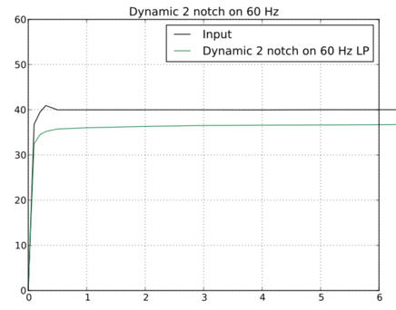
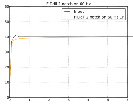
The third set of
filters is mechanized using an open-source filter module (FIDlib)
which is also used by some other neurofeedback manufacturers. The
specific filter types EEGer4 uses with FIDlib are BsBu (Bandstop
Butterworth), BpBu (Bandpass Butterworth), and LpBu
(LowpassButterworth). These filters all use the following
specifications:
order= 2 to 8
width specified at
-3db points (.707 of peak)
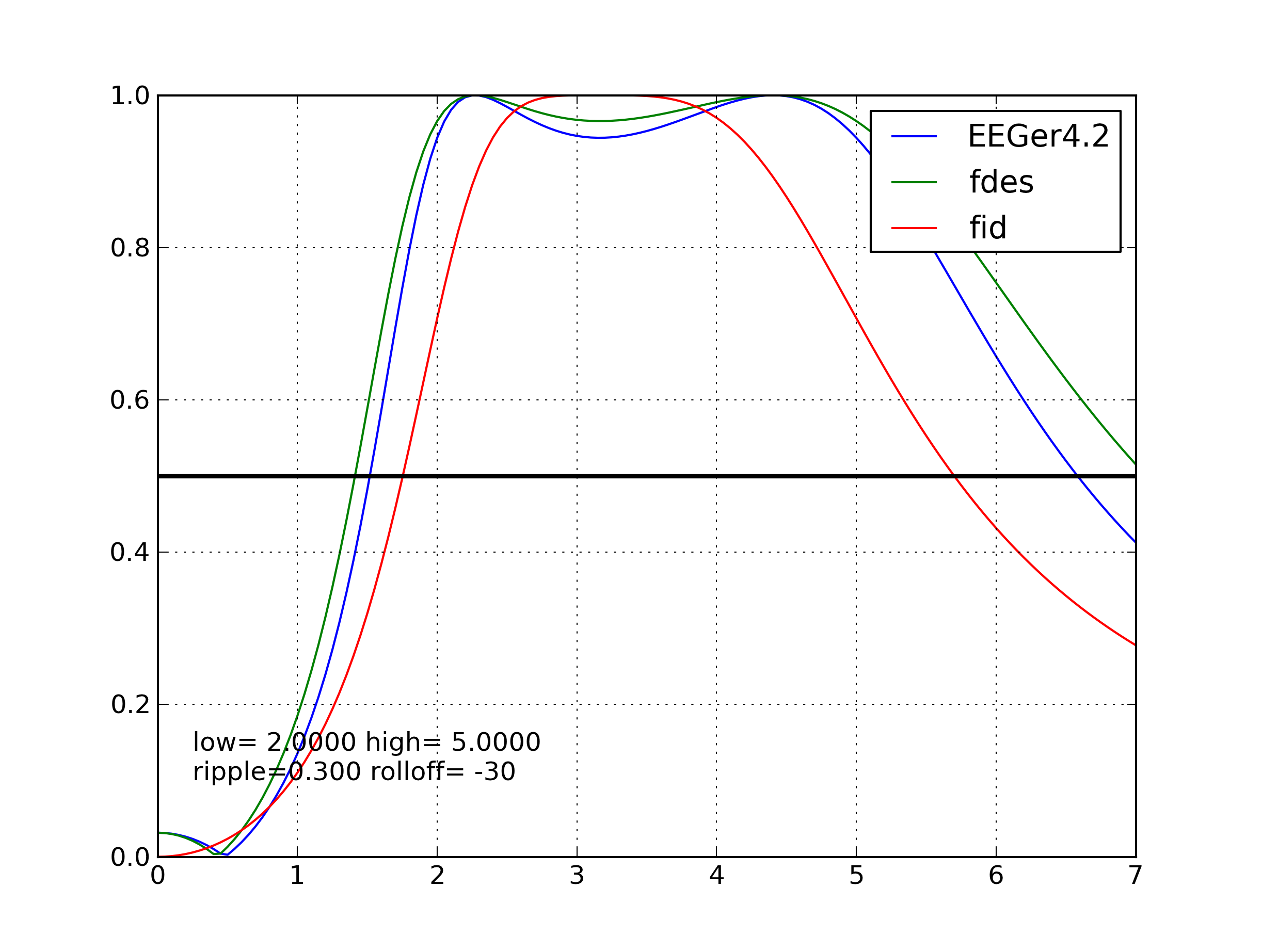
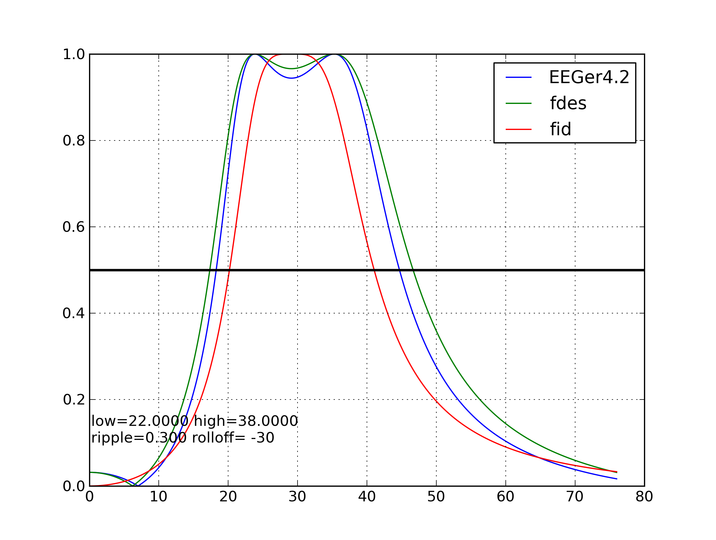
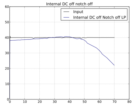
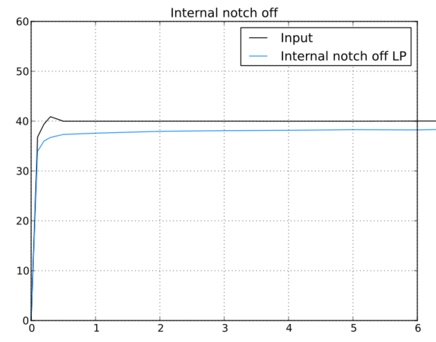
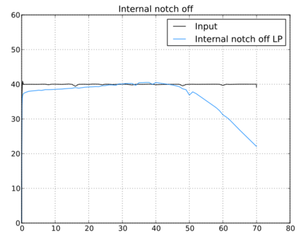
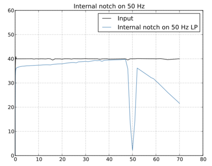
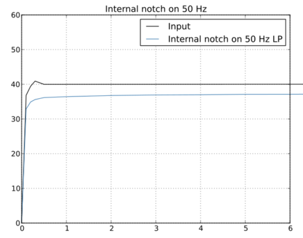
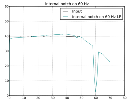
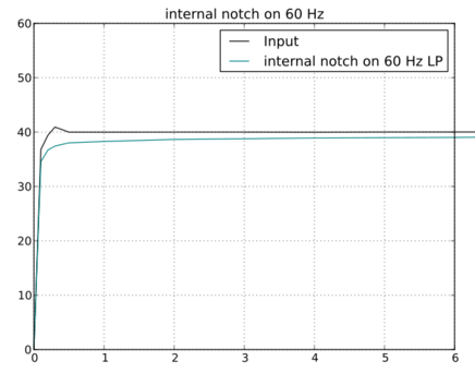
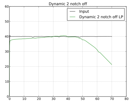
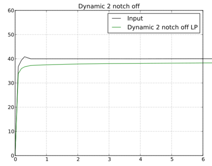
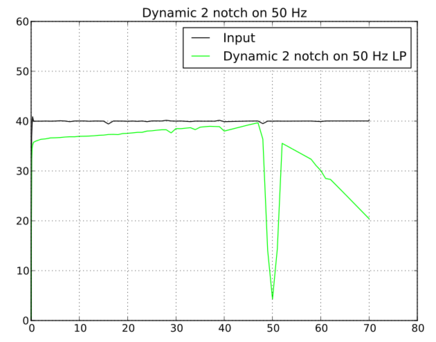
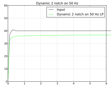
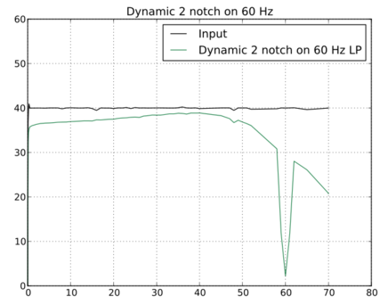
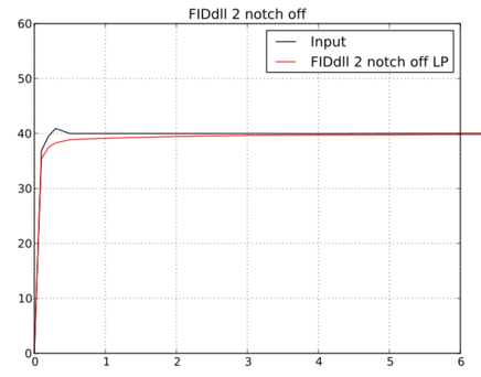
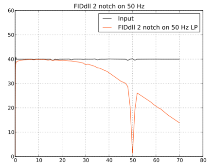
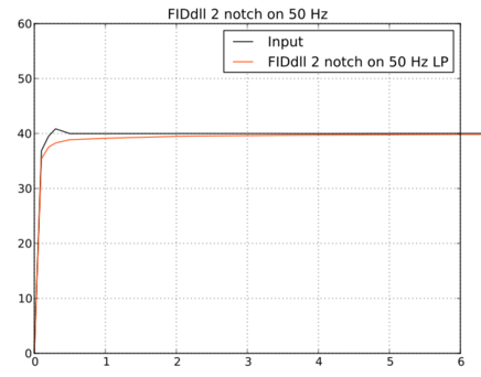
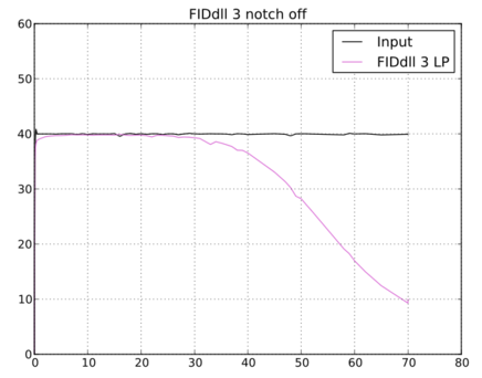
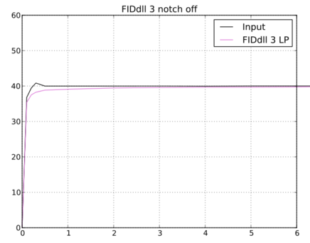
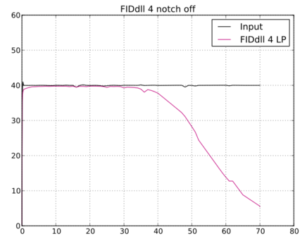
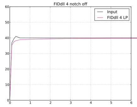
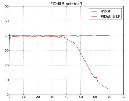
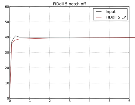
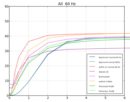
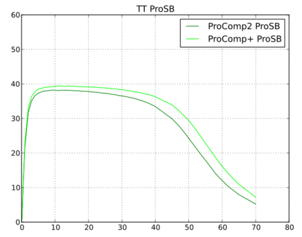
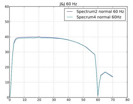
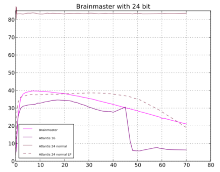
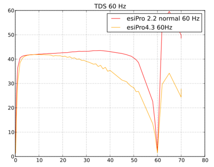
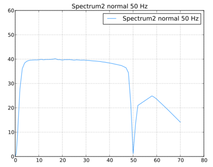
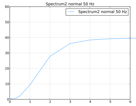
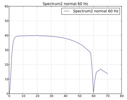
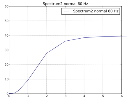
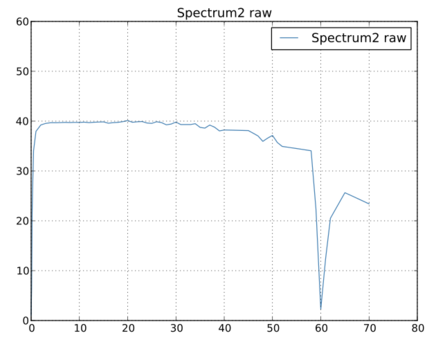
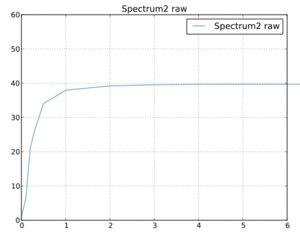
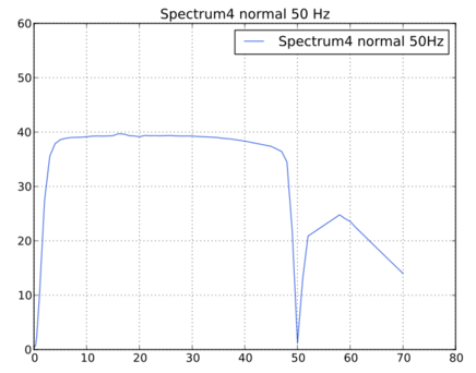
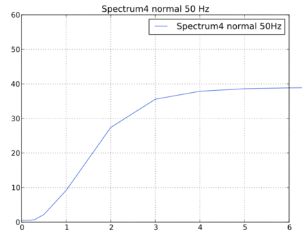
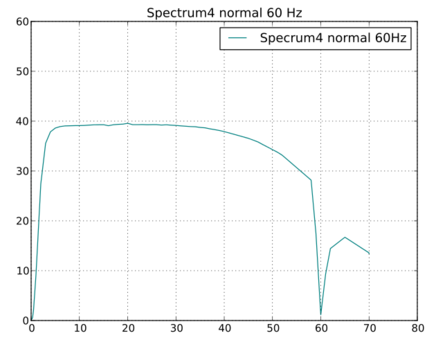
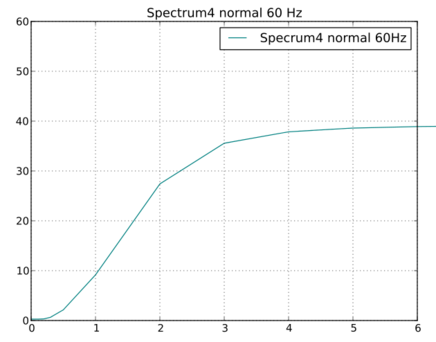
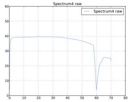
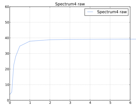
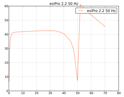
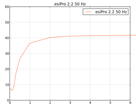
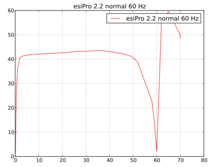
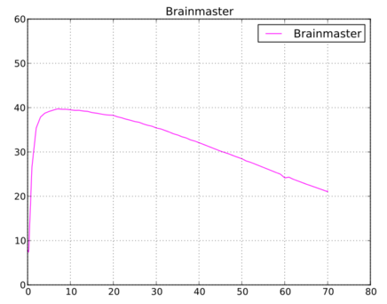
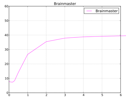
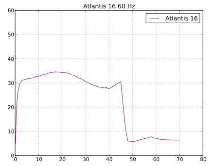
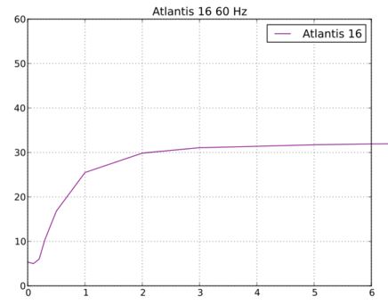
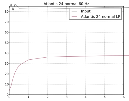
A comparison of
the three methods is shown in Figures 1,2,3,4.
Figure
1
Figure
3
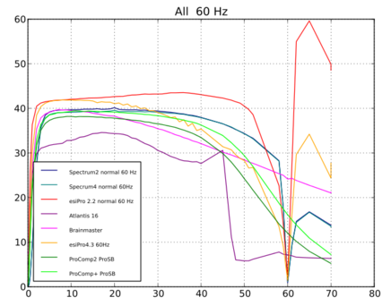
Here is a
comparison of the filter sets for various orders:
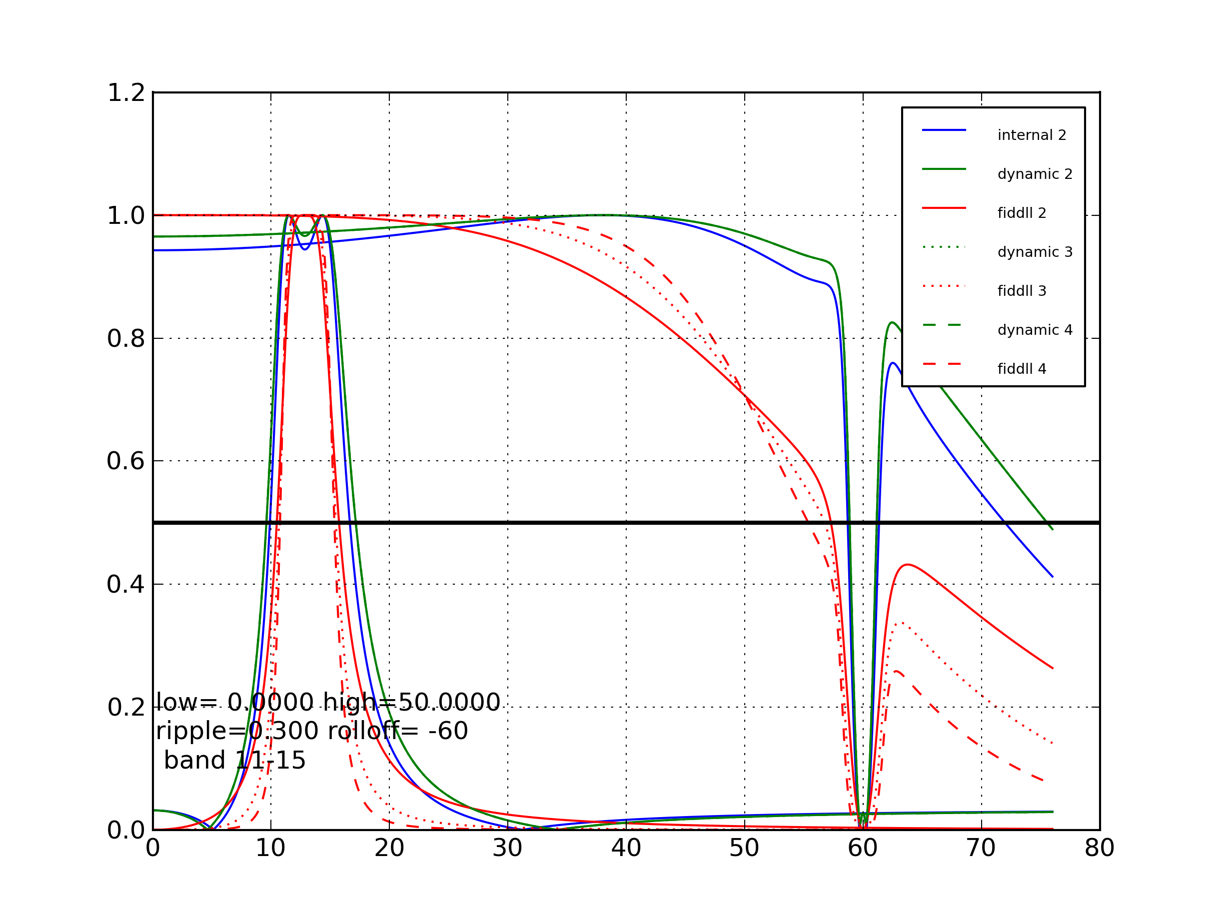
Figure
4
Note that the
EEGer4 frequency specifications are to the edges of the flat
response while the FIDlib specifications are to the -3db points.
Full bandpass characteristics are shown for each filter method are
shown in Appendix A. Appendix E describes the methodology used to
acquire this data.
Acquisition Components
EEGer4 supports
amplifier/encoder components from many manufacturers. Each
component has (or may have) different frequency response
characteristics. The following encoder/amplifiers are supported by
EEGer4 (Pass/Fail/Untested noted in the last column):
|
Device Name
|
Manufacturer
|
Hardware Interface
|
Interface method
|
Support status
|
EEG Channels Supported
|
P/F
|
|
BrainLynx
|
J&J Engineering
|
USB
|
Mfr DLL
|
Currently supported
|
2
|
P
|
|
C2mini
|
J&J Engineering
|
USB
|
Mfr DLL
|
Obsolete/ supported
|
2
|
U
|
|
C2
|
J&J Engineering
|
USB
|
Mfr DLL
|
Obsolete/ supported
|
2
|
U
|
|
C2+mini
|
J&J Engineering
|
USB
|
Mfr DLL
|
Currently supported
|
2
|
P
|
|
C2+
|
J&J Engineering
|
USB
|
Mfr DLL
|
Currently supported
|
2
|
P
|
|
Spectrum 2
|
J&J Engineering
|
USB
|
Mfr DLL
|
Currently supported
|
2
|
P
|
|
Spectrum 4
|
J&J Engineering
|
USB
|
Mfr DLL
|
Currently supported
|
2/4
|
P
|
|
GP8e
|
Physiocom
|
USB
|
MFR DLL
|
Currently supported
|
2A202
|
P
|
|
GP12e
|
Physiocom
|
USB
|
MFR DLL
|
Currently supported
|
2/4
|
P
|
|
|
|
|
|
|
|
|
|
esiPro 2.2
|
TeleDiagnostic Systems
|
USB
|
Mfr DLL
|
Currently supported
|
2
|
P
|
|
esiPro 4.3
|
TeleDiagnostic Systems
|
USB
|
Mfr DLL
|
Currently supported
|
2/4
|
P
|
|
A200
|
Phoenix Neuro Systems
|
USB
|
Mfr DLL
|
Currently supported
|
2
|
P
|
|
A400
|
Phoenix Neuro Systems
|
USB
|
Mfr DLL
|
Currently supported
|
2/4
|
P
|
|
A202
|
Southeast Signal
|
USB
|
Mfr DLL
|
Currently supported
|
2
|
P
|
|
A404
|
Southeast Signal
|
USB
|
Mfr DLL
|
Currently supported
|
2/4
|
P
|
|
|
|
|
|
|
|
|
|
ProComp2
|
Thought Technology
|
Serial port
|
Internal code (serial interface)
|
Currently supported
|
2
|
P
|
|
ProComp+
|
Thought Technology
|
Serial port
|
Internal code (serial interface)
|
Currently supported
|
2
|
P
|
|
Infiniti
|
Thought Technology
|
Serial port
|
Internal code (serial interface)
|
Currently supported
|
2
|
P
|
|
ProComp5
|
Thought Technology
|
Serial port
|
Internal code (serial interface)
|
Currently supported
|
2
|
U
|
|
ProComp2
|
Thought Technology
|
USB
|
Mfr DLL
|
Currently supported
|
2
|
P
|
|
ProComp+
|
Thought Technology
|
USB
|
Mfr DLL
|
Currently supported
|
2/4
|
P
|
|
Infiniti
|
Thought Technology
|
USB
|
Mfr DLL
|
Currently supported
|
2/4
|
P
|
|
ProComp5
|
Thought Technology
|
USB
|
Mfr DLL
|
Currently supported
|
2/4
|
U
|
|
|
|
|
|
|
|
|
|
Brainmaster 2E
|
Brainmaster
|
Serial port
|
Mfr DLL
|
Currently supported
|
2
|
P
|
|
Atlantis 2
|
Brainmaster
|
USB with serial port
|
Mfr DLL
|
Currently supported
|
2
|
P
|
|
Atlantis 4
|
Brainmaster
|
USB with serial port
|
Mfr DLL
|
Untested/
no device but same DLL as all Brainmaster devices
|
2/4
|
U
|
|
Discovery
|
Brainmaster
|
USB with serial port
|
Mfr DLL
|
Under test/
no device
|
2/4 (24)
|
U
|
|
|
|
|
|
|
|
|
|
Pet2.0
|
Brainquiry
|
Bluetooth serial
|
Internal code (serial interface)
|
Obsolete/
no device but previously supported
|
2
|
U
|
|
QPET
|
Brainquiry
|
Bluetooth serial
|
Mfr DLL
|
Obsolete/
no device but previously supported
|
2
|
U
|
|
|
|
|
|
|
|
|
|
Pendant-EEG
|
Pocket-Neurobics
|
Bluetooth serial
|
Internal code (serial interface)
|
Under test/
no device but previously supported
|
2
|
U
|
|
UWiz
|
Pocket-Neurobics
|
Bluetooth/
USB
|
Generic driver
|
Currently supported
|
2
|
P
|
|
QWiz
|
Pocket-Neurobics
|
Bluetooth/
USB
|
Generic driver
|
Currently supported
|
2/4
|
P
|
|
|
|
|
|
|
|
|
|
Q20/Q21
|
Neurofield
|
CAN
|
Mfr DLL
|
Currently supported
|
2/4 (24)
|
P
|
|
|
|
|
|
|
|
|
|
CQuick
|
|
|
Mfr DLL
|
Under test/
no device
|
2/4
|
U
|
|
|
|
|
|
|
|
|
|
Optima
|
Neurobit
|
Bluetooth/USB
|
Mfr DLL
|
Currently supported
|
2/4
|
P
|
|
|
|
|
|
|
|
|
|
(external amplifier)
|
------------------
|
USB
|
A/D device supported by Measurement Computing Corporation
InstaCal software
|
Currently supported (used for system testing)
|
2/4
|
P
|
The acquisition
devices use a variety of interface methods, usually serial,
Bluetooth, or USB connections. Each device manufacturer has a
custom interface method. EEGer has interface modules written to
support all the above devices using either direct programming or
the device manufacturer's provided interface methodology (i.e. DLL
or other interface program). All the devices from J&J
Engineering use a common interface DLL, differing only by a command
code, and a common EEGer interface module.. All the C2+ based
devices (including BrainLynx and Spectrum 2/4) use a single command
code (and a common printed circuit board). All the devices from
Brainmaster use a common DLL and s single EEGer interface module.
All the Thought Technology devices using serial interfaces use
generic Windows serial interfaces and a single EEGer interface
module. All the Thought Technology devices using the USB (TTUSB)
interface use a common DLL and a single EEGer interface module.
Since the interfaces are common between device models, extensive
testing was only necessary for devices using each interface. A
simpler test was used to confirm that the other models supported
could also communicate across the interface.
Appendix B
contains the bandpass characteristics of these components. These
bandpass characteristics are in addition to the filter
characteristics of whatever filter method and frequency band
selected.
Appendix E
contains the methodology used to acquire the test data for Appendix
A and B.
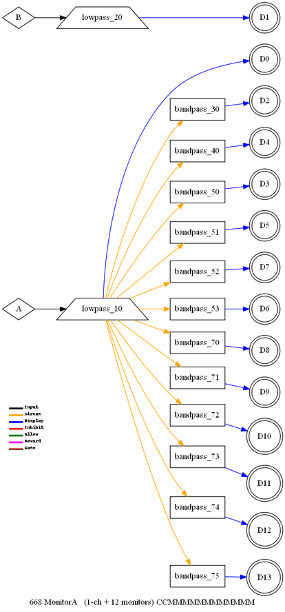
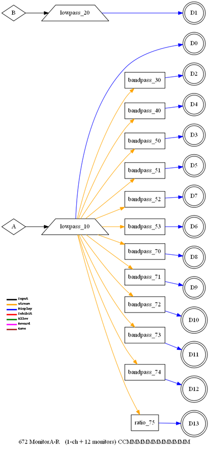
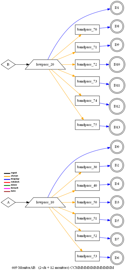
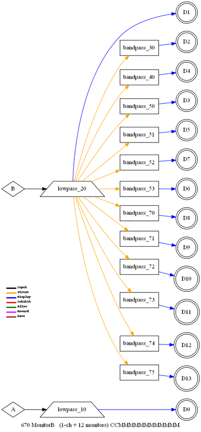
Layout and Feedback Modes
EEGer4 provides a
number of screen configurations (called “layouts”) of EEG data.
Each layout has a
number of “feedback modes” with predefined usage of each element of
the screen.
All layouts have
two or four lowpass EEG traces at the top of the screen and some
number of additonally filtered traces below.
The current list
of layouts (and the short titles) is:
5= 5-trace
6i= 6-trace,inhibit
6r= 6-trace,reward
8= 8-trace
14= 14-trace
14x4= 14-trace,monitor
14a= ChanA,screen
14ab= 2-chan,screen
14b= ChanB,screen
5r= Reward-only
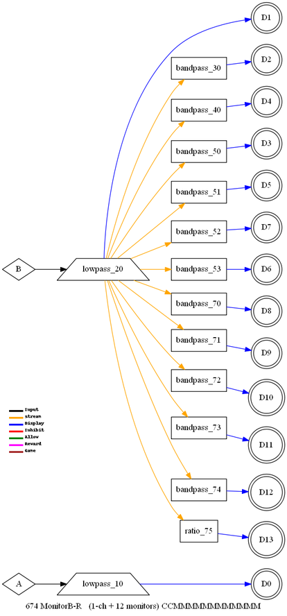
6m= 6-trace,monitor
7m= 7-trace,monitor
7im=7 trace,monitpr 3 inhibit, 1 reward
8z= 8-trace-4zcomp
8p= 8-trace-2-rewards
8q=8-trace,1reward
10c=10-trace,coherences
10r=10-trace,ratios
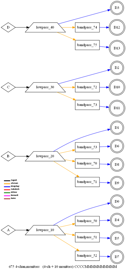
12=4 chan,4 monitor, 1 reward, 3 inhibit
12x=4 chan,4 reward, 4 inhibit
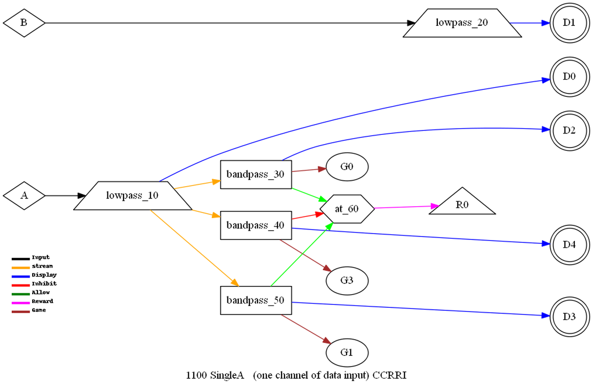
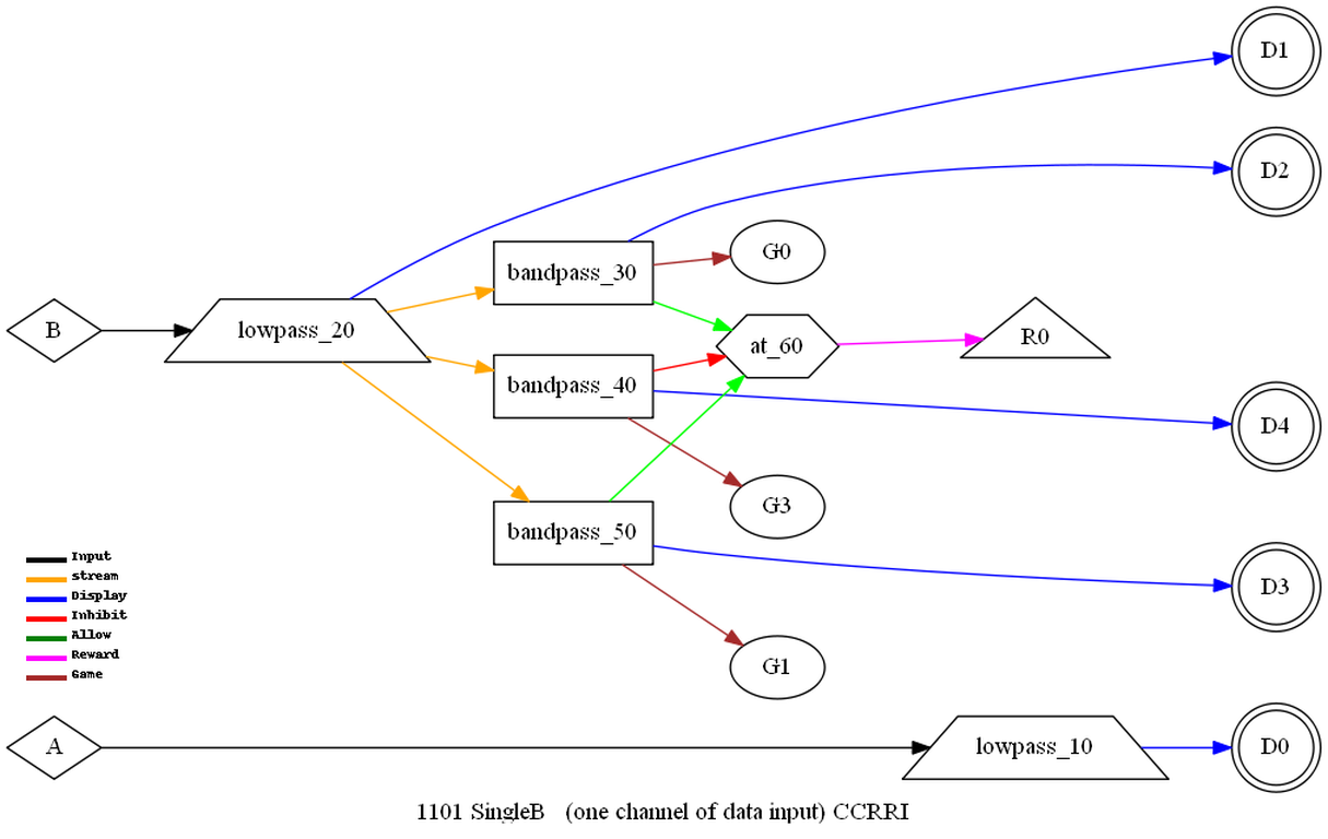
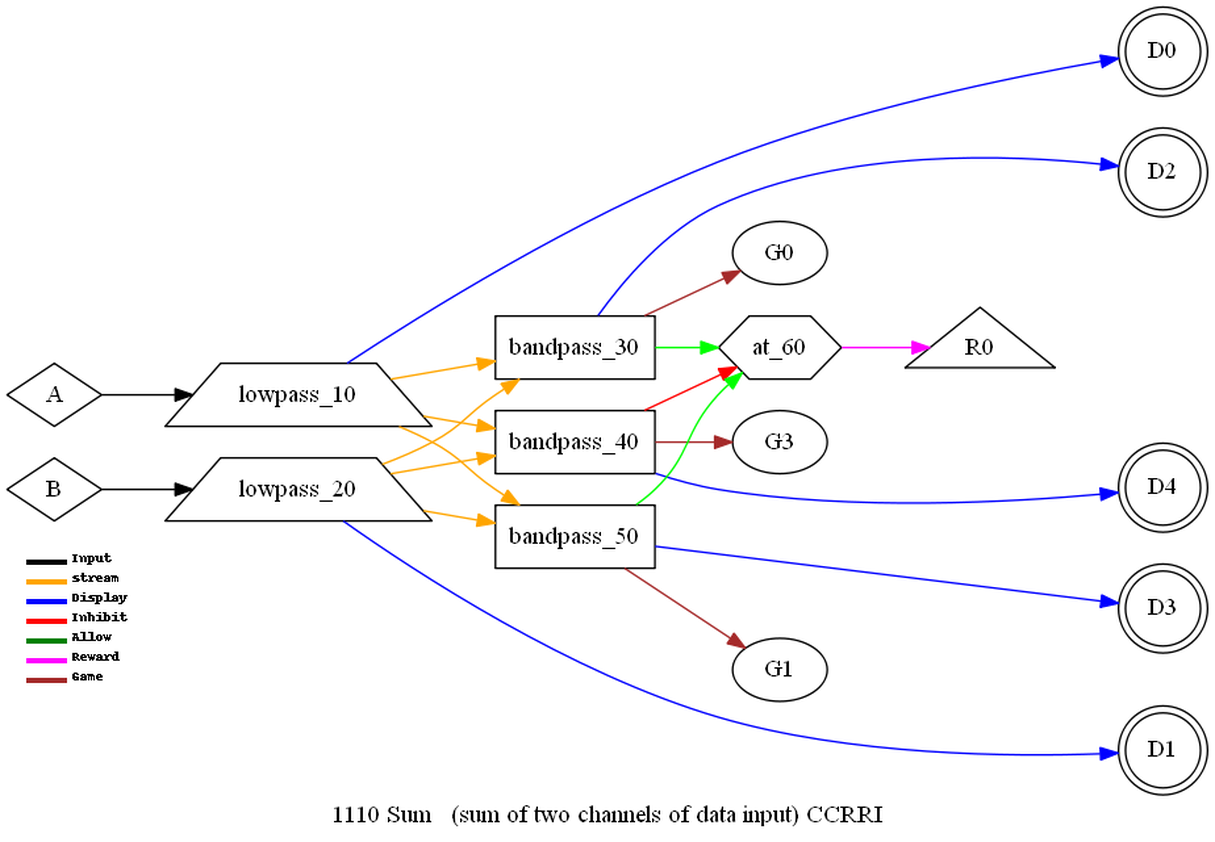
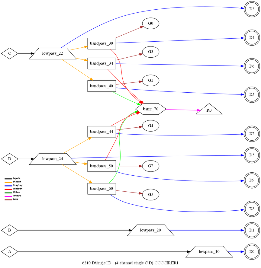
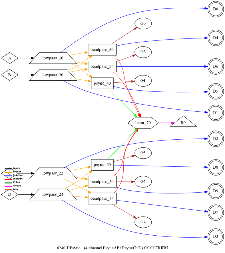
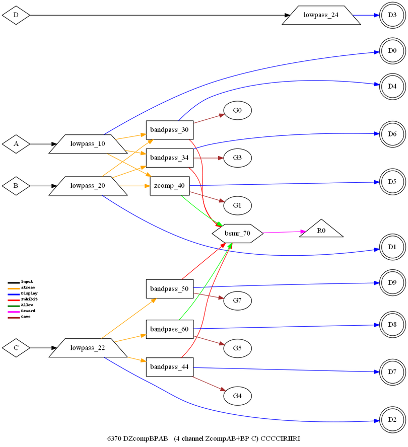
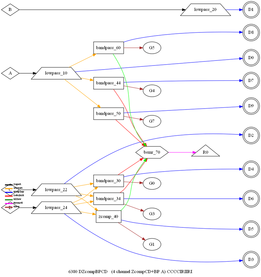
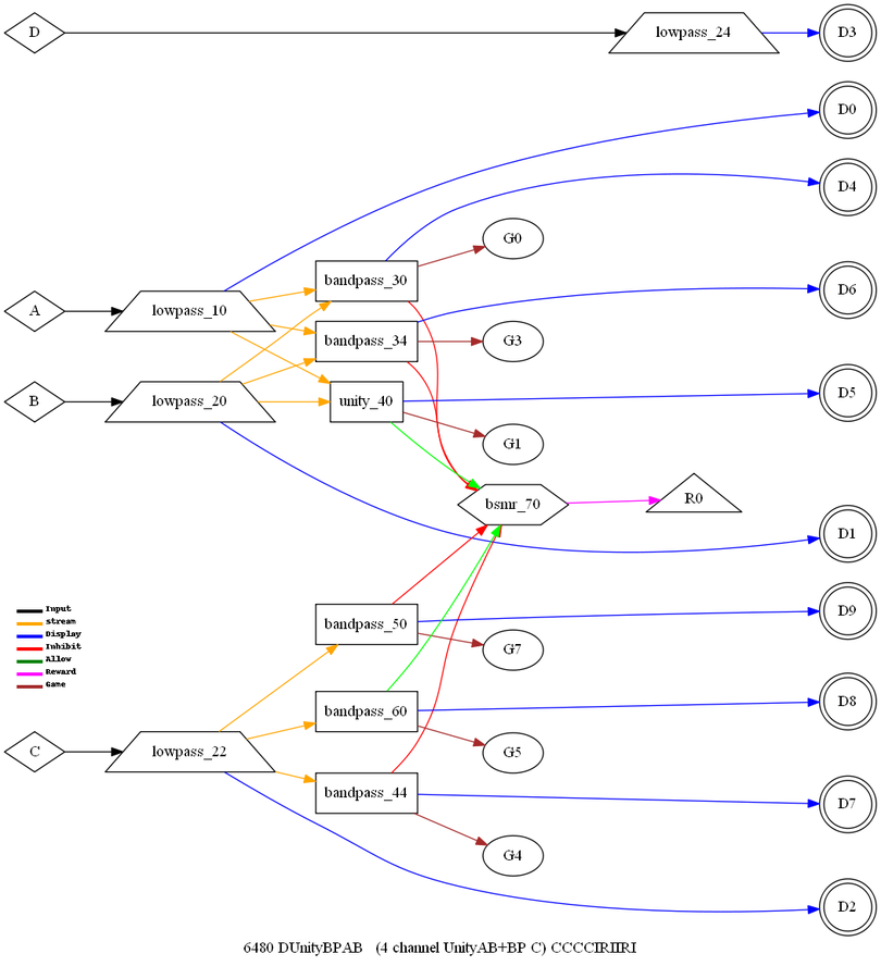
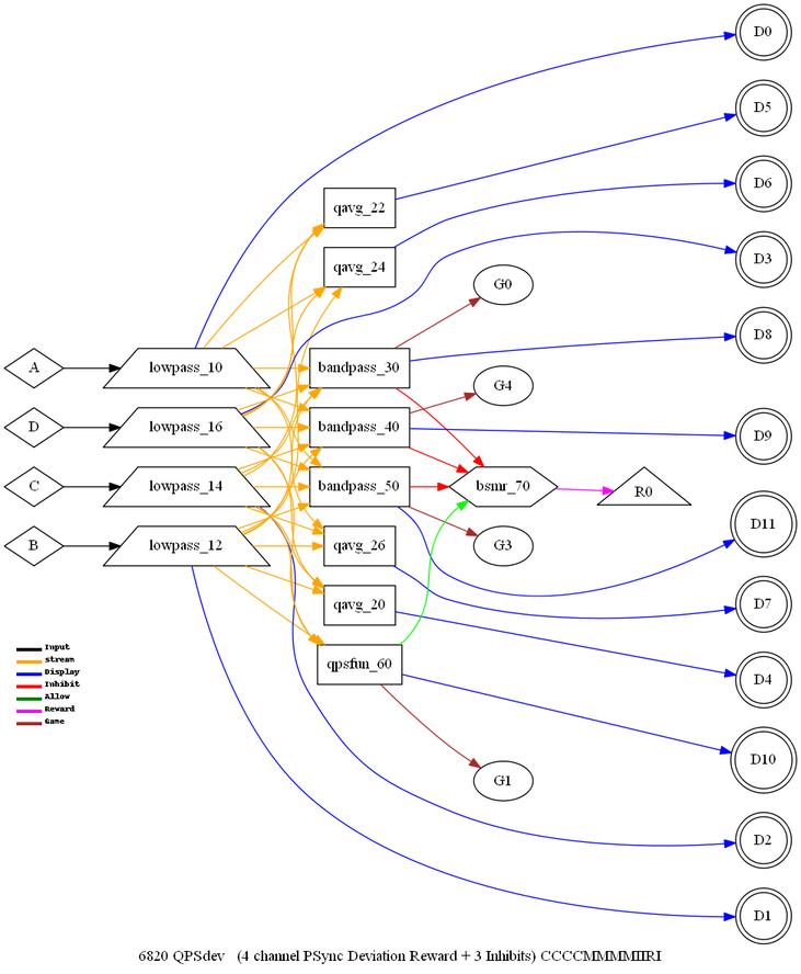
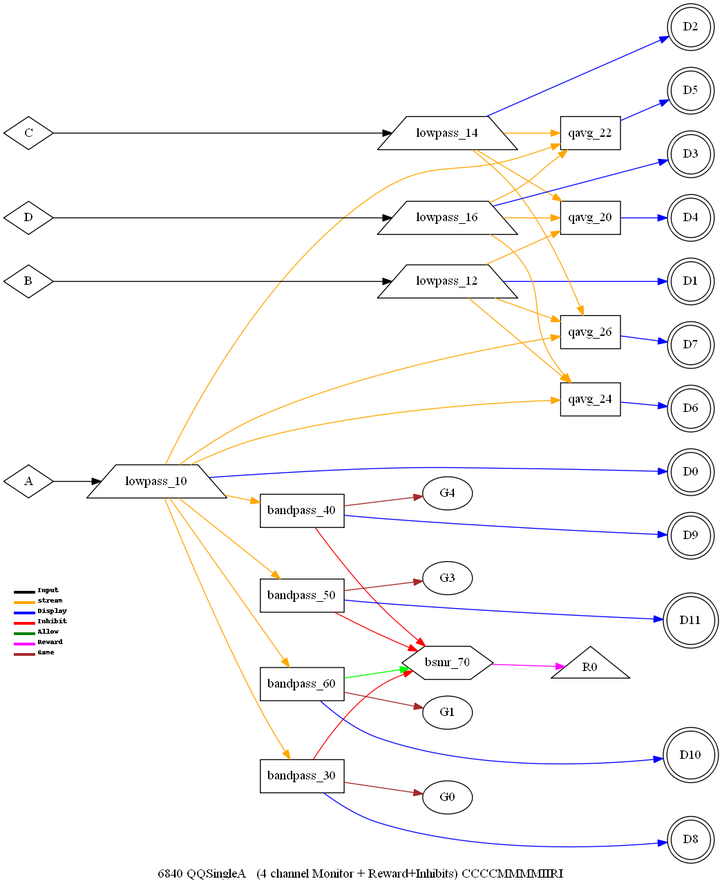
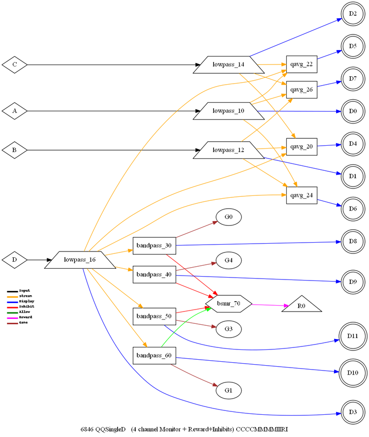
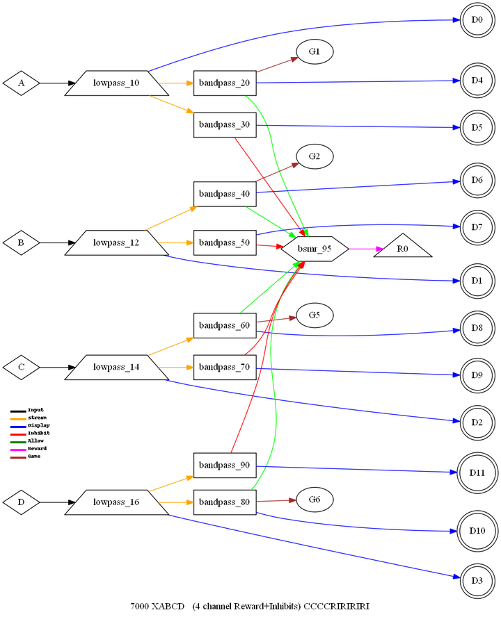
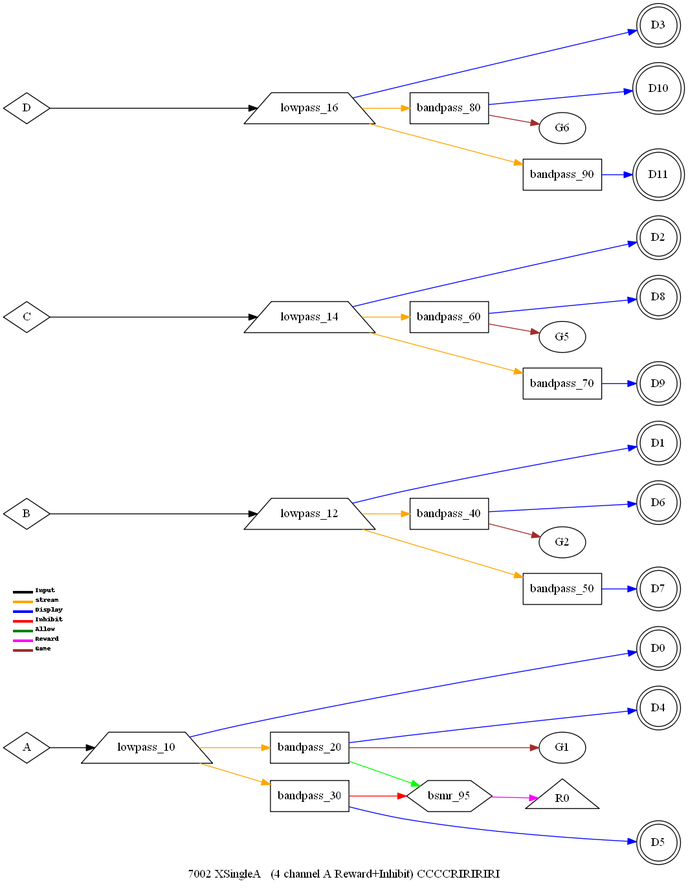
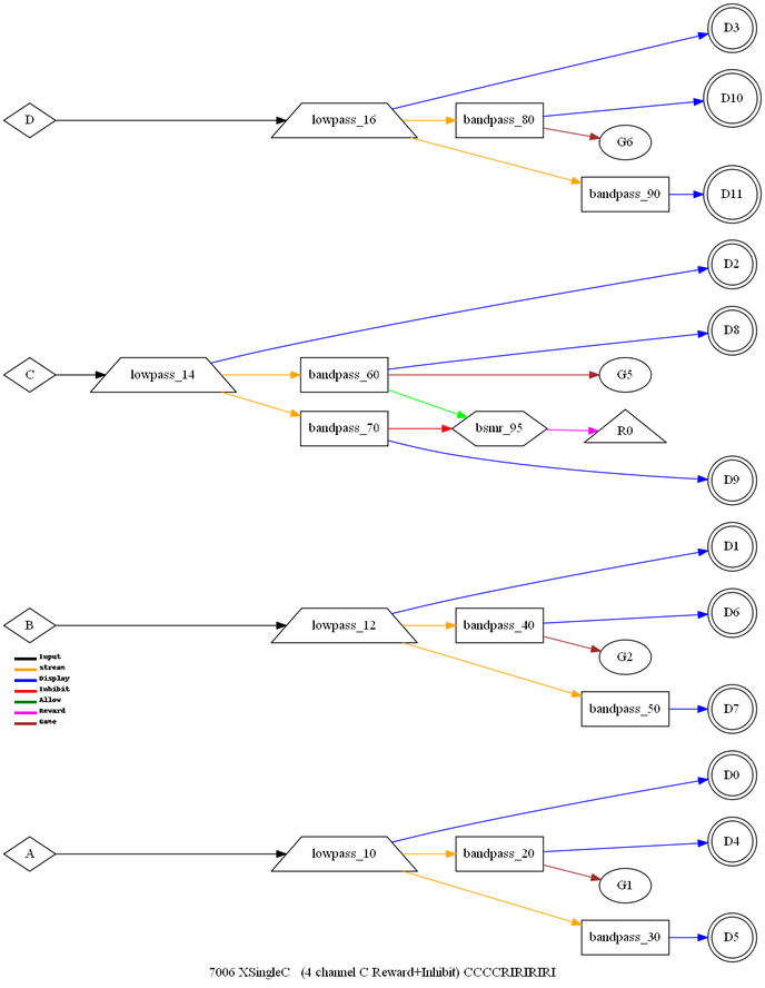
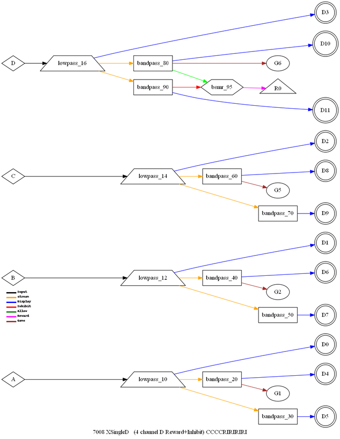
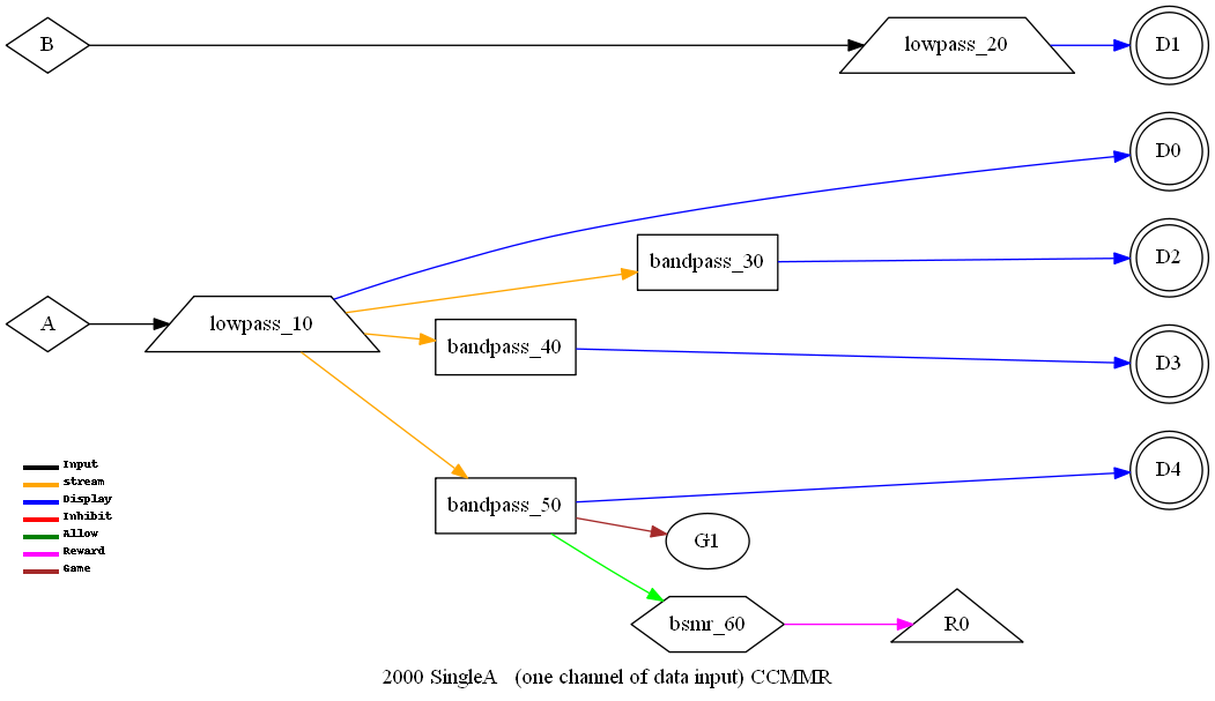
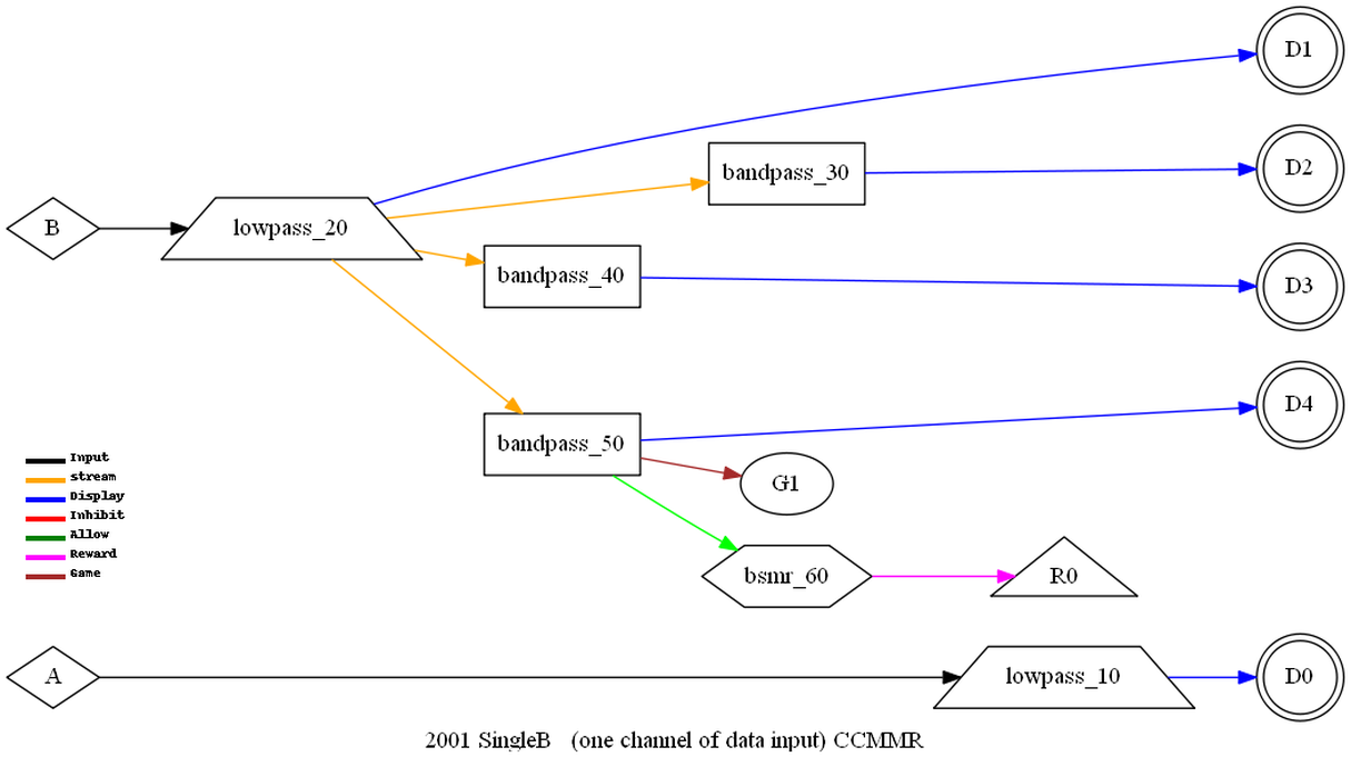
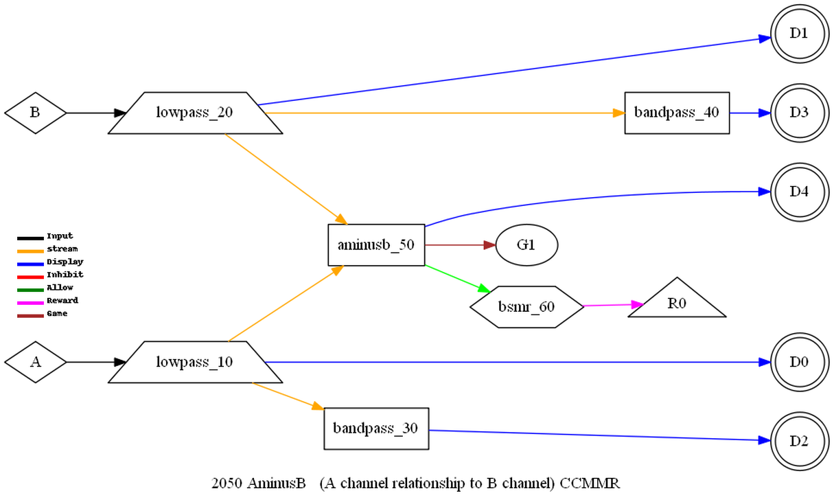
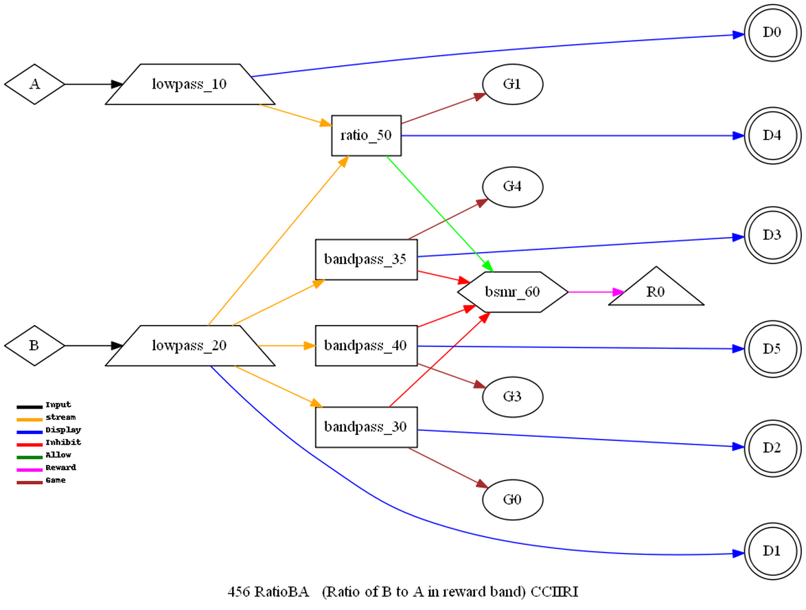
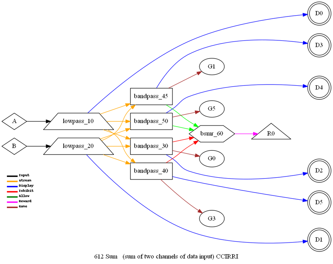
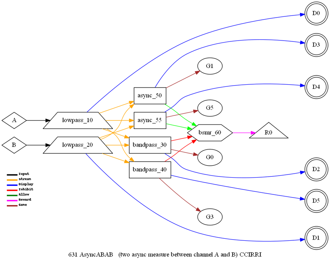
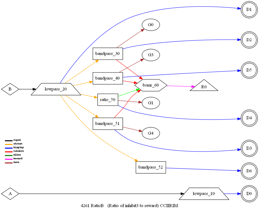
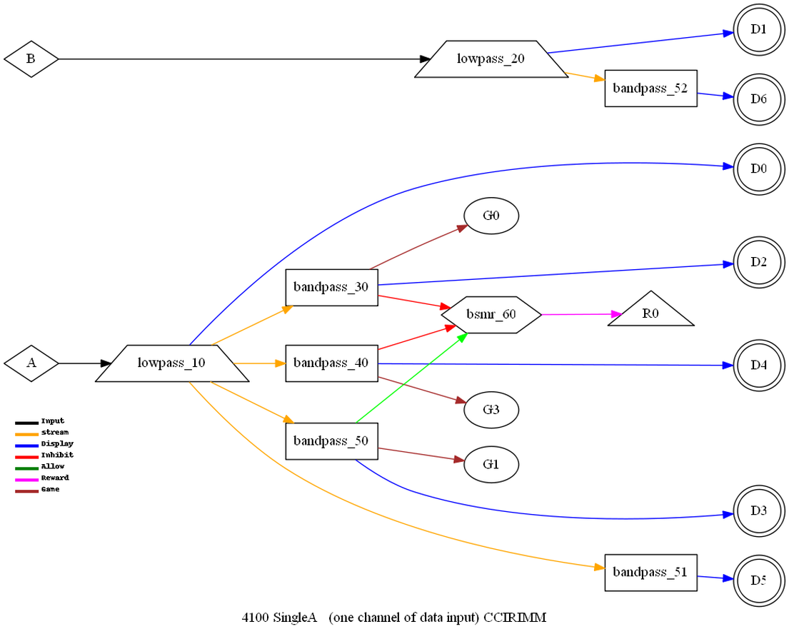
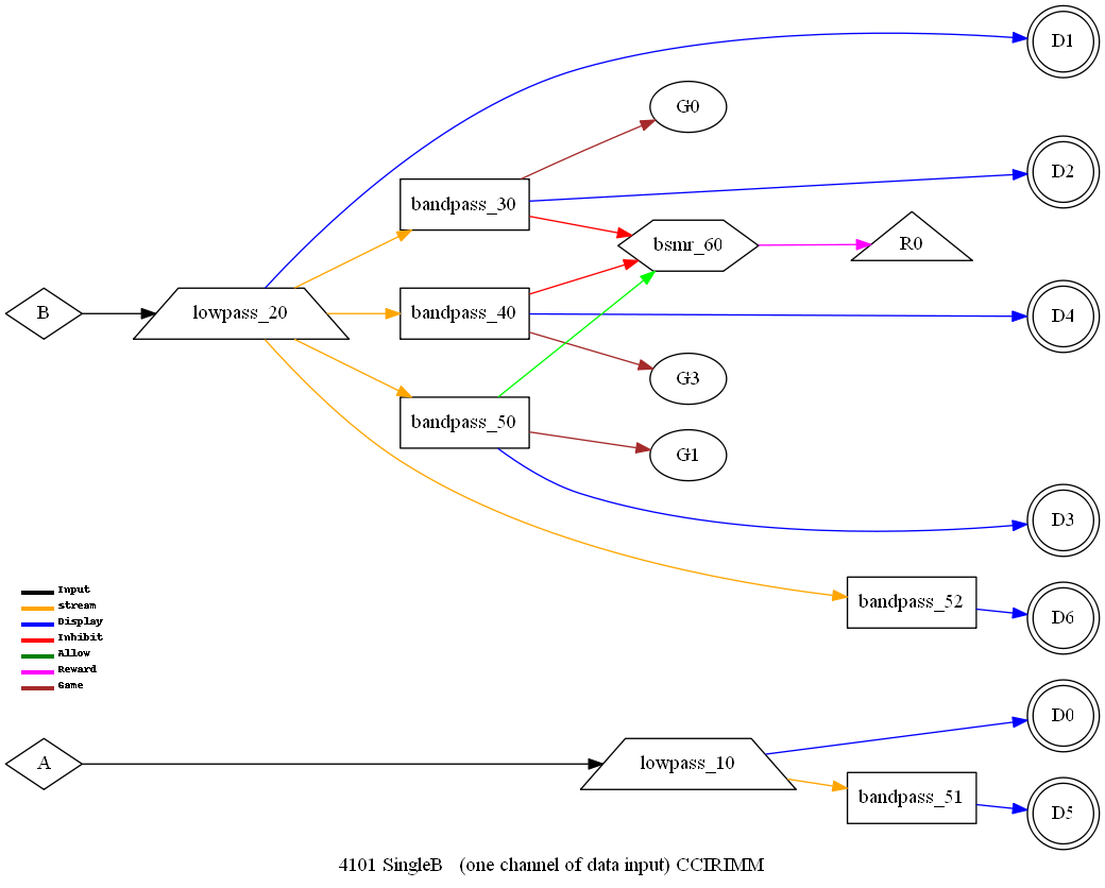
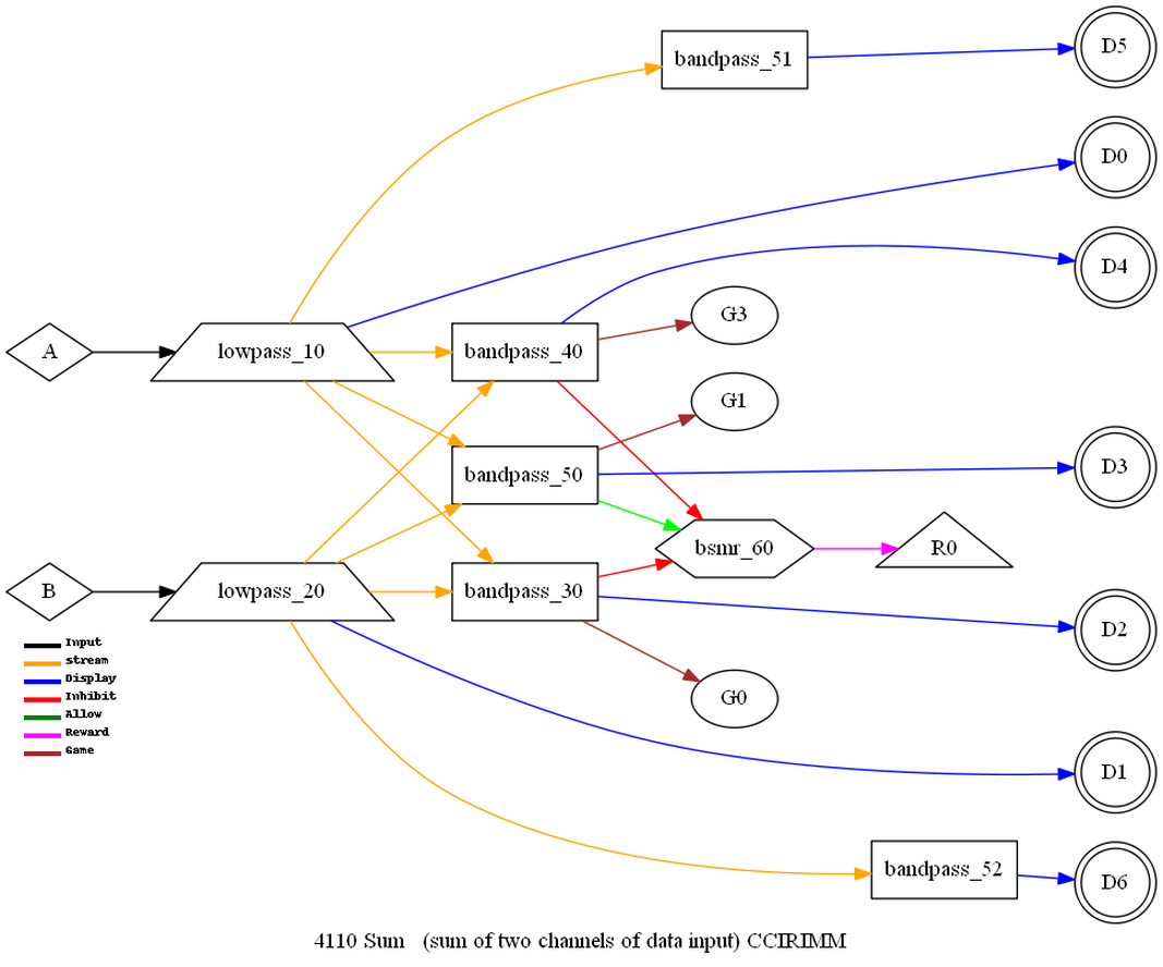
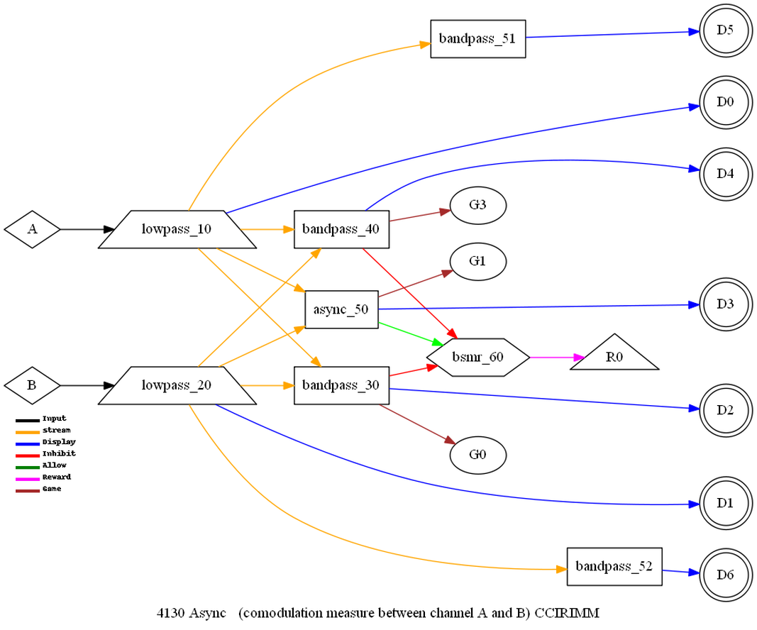
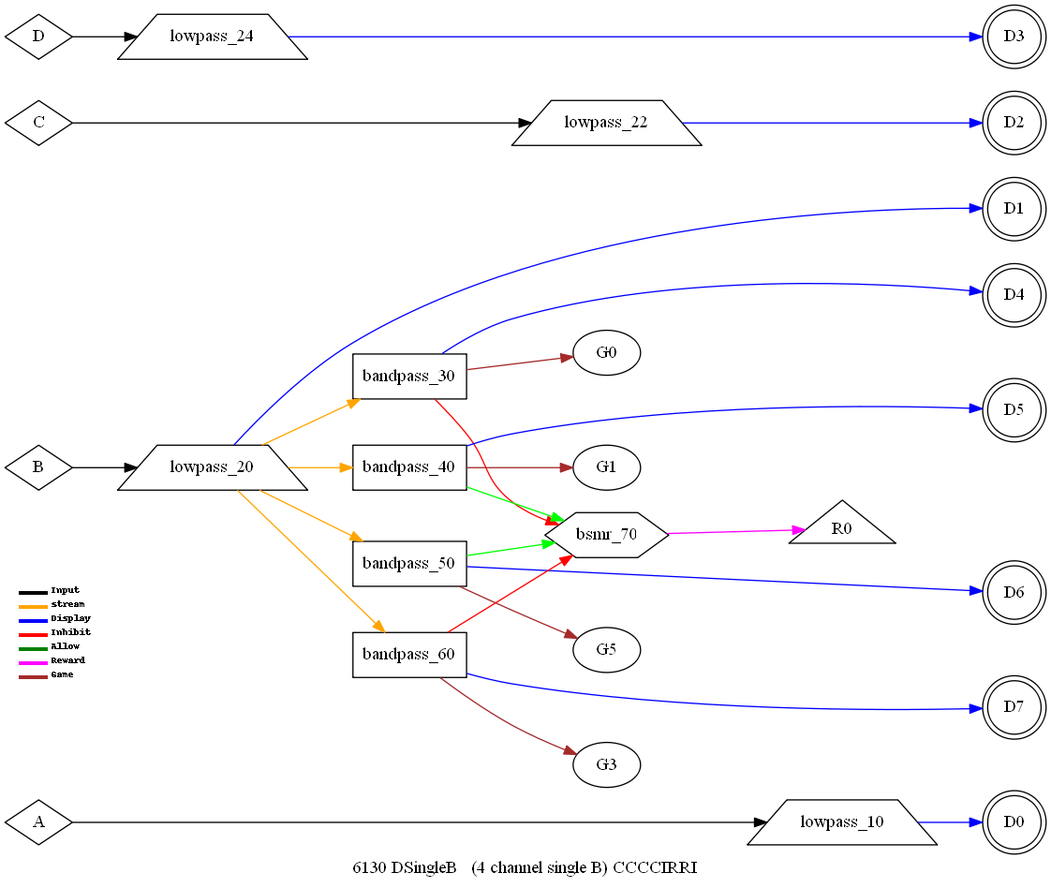
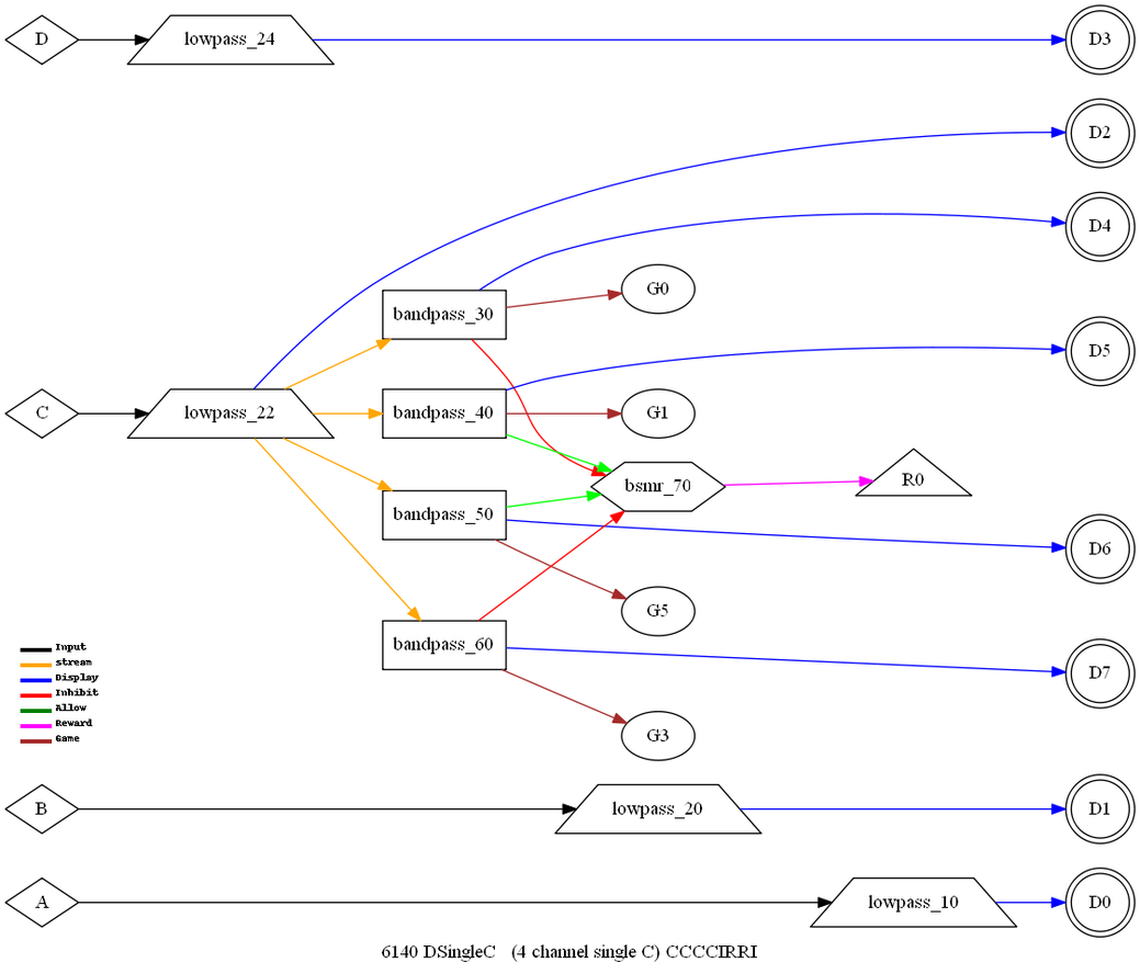
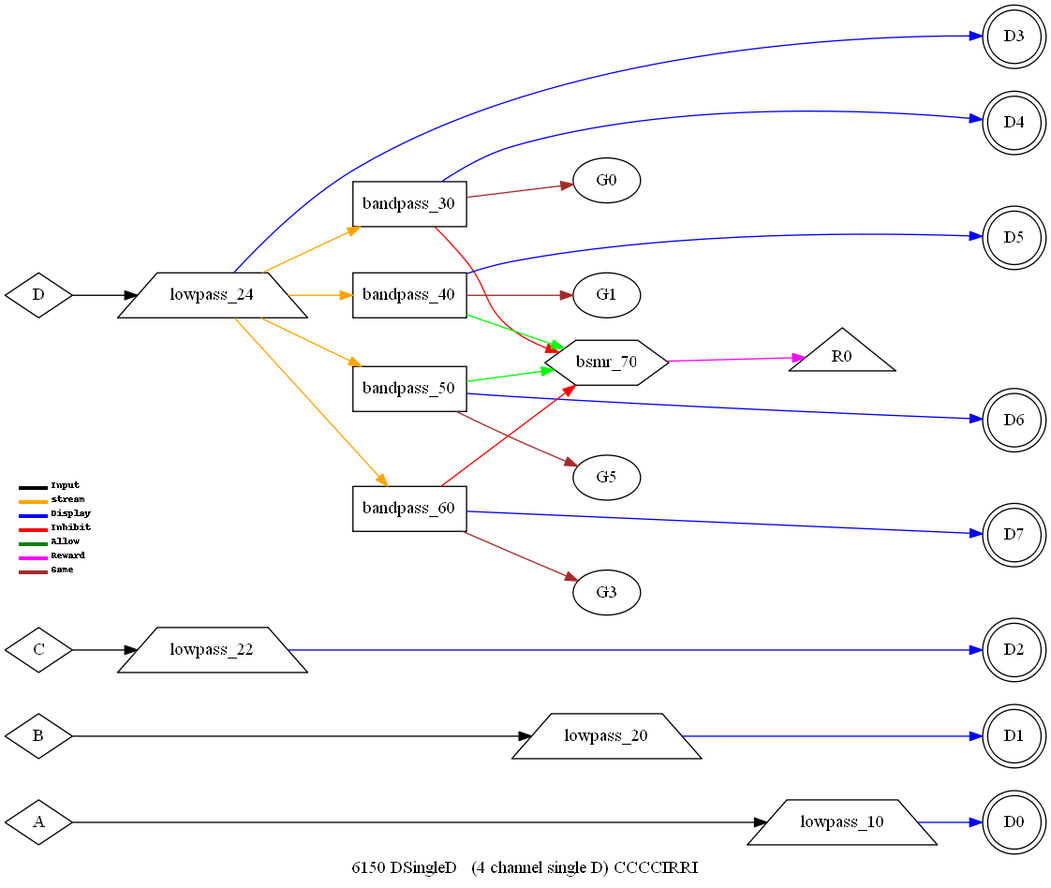
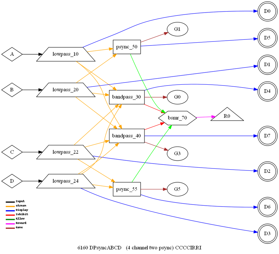
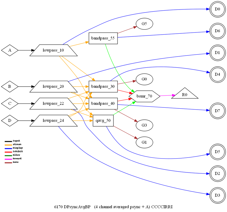
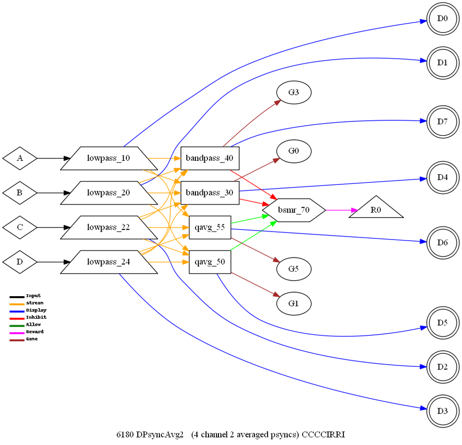
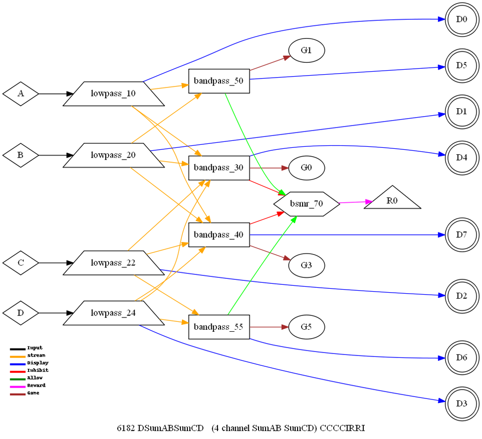
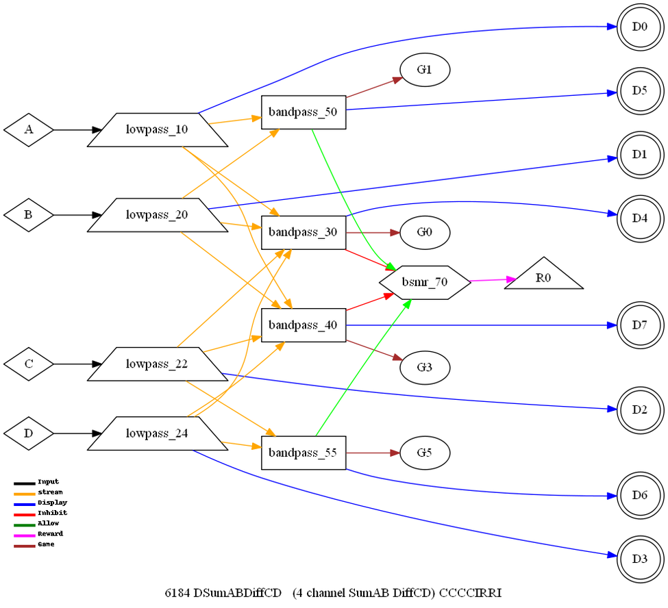
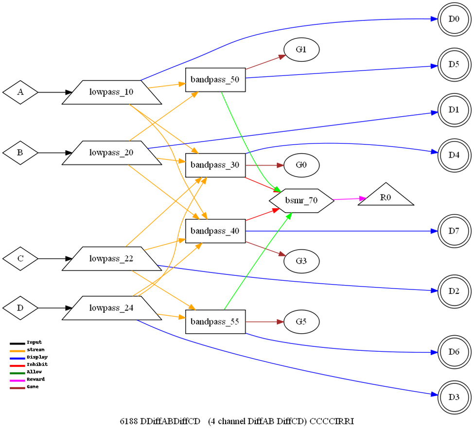
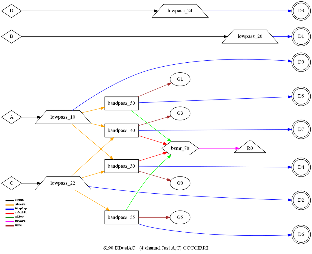
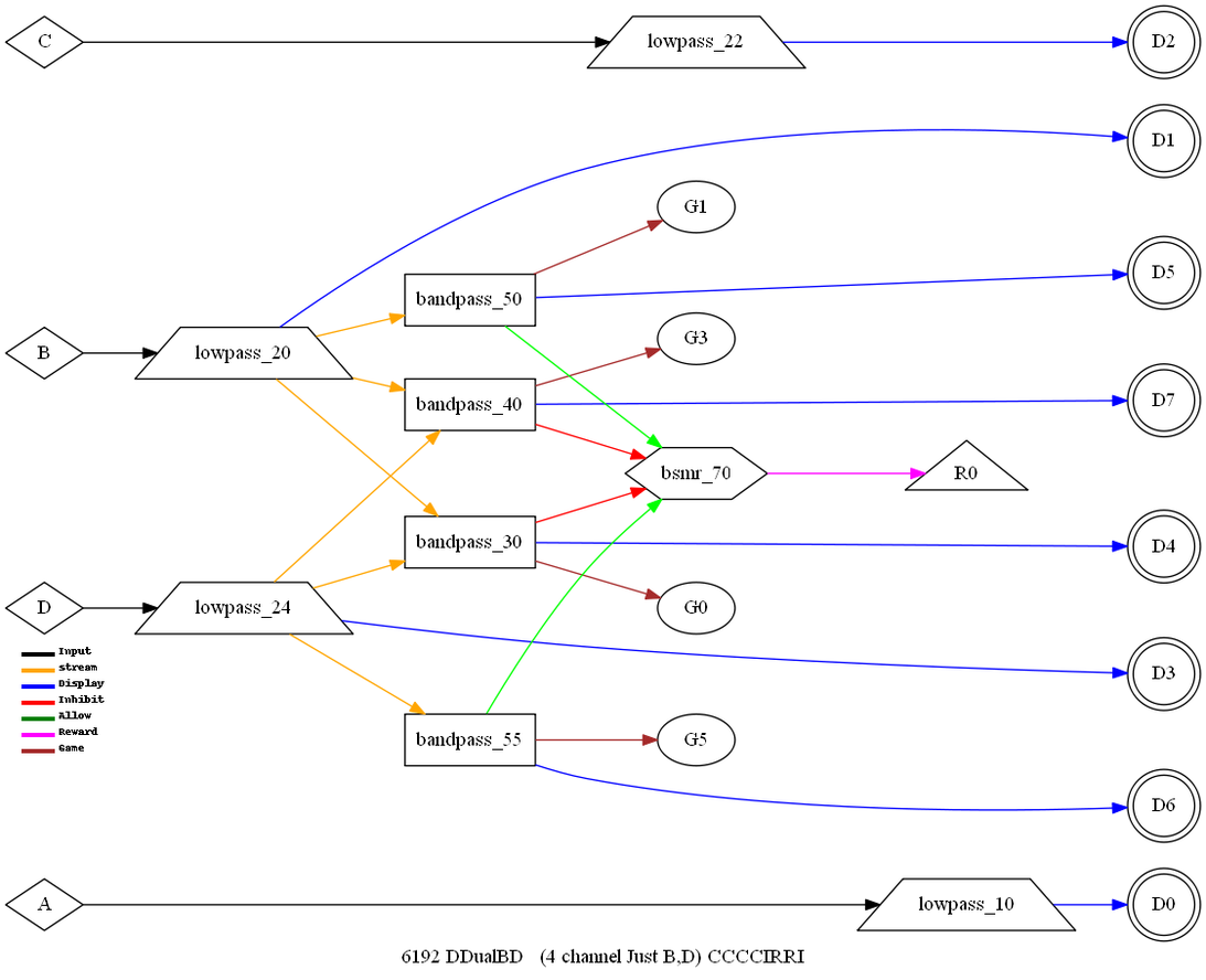
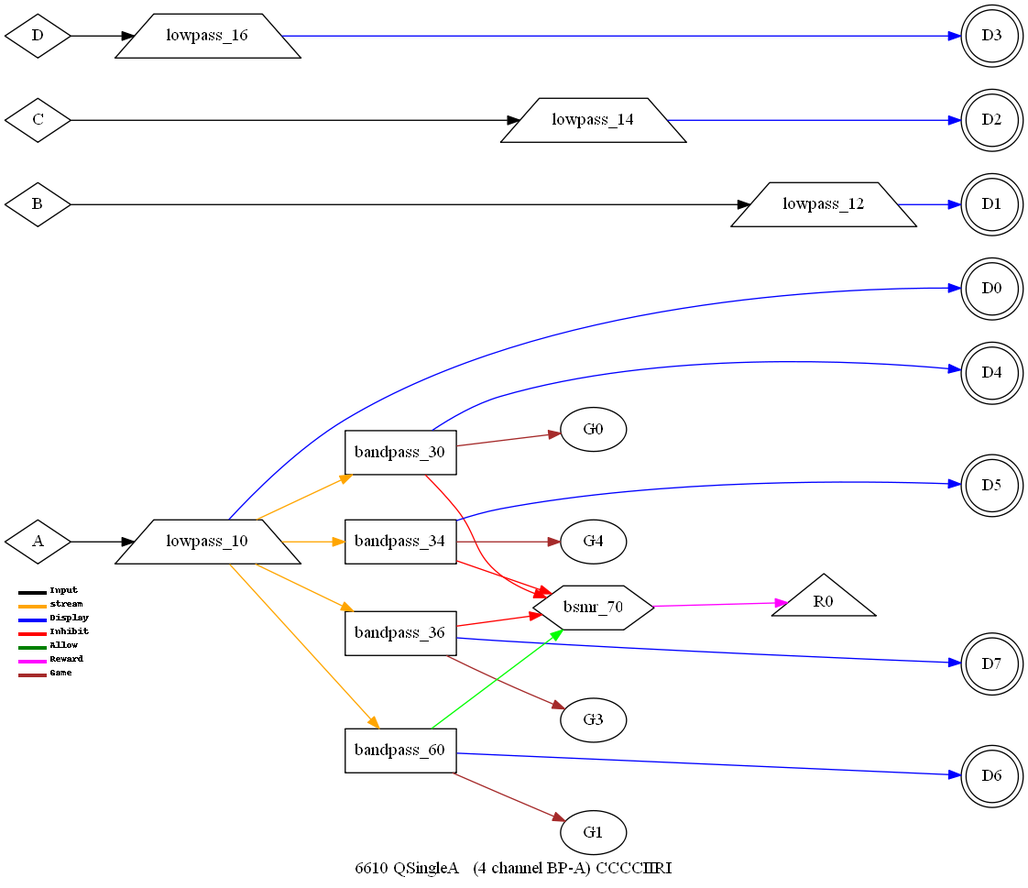
Each feedback mode
(internally) consists of a sequence of filter operations and
decisions tied to particular elements (traces both visible and
invisible) of the layout. Appendix C has the block diagrams of each
of these feedback modes. The operation blocks on those diagrams use
the following operations/decisions (names shown in bold).
Certain generic operations are used. Most importantly, smoothing is
performed using an Exponentially-Weighted-Moving-Average (EWMA)
filter characterized by
Equation
2
Also, a threshold
decision is made using a comparison between a short-term (EWMA)
average and a user-specified threshold value.
lowpass
Lowpass filter and
DC correct a raw input from an acquisition component.
The input value is
compared to the current “artifact threshold” to determine if the
data is a spike (short term amplitude value) or artifact (longer
term amplitude value). If the signal is determined to be an
“artifact” (probably due to eyeblinks, muscle motion, etc.), a zero
value is the output of the operation. Once in an artifact
condition, that condition will be held for a short time after the
condition disappears (allowing the data to stabilize). If the input
is NOT an artifact, the input value is lowpass filtered. The output
of the filter is DC-corrected (to center the data display) and is
the output of this operation. It is also integrated using an EWMA
filter with a short-term, user-specified time constant (typically
0.5 seconds, with a range of 0.1 to 0.9 seconds).
bandpass
Bandpass filter a lowpass data sample and check for target
threshold.
The
input value is bandpass filtered. The signal is integrated using an
EWMA for comparison with the target threshold. This block has
several outputs: the signal, the 'average' value (actually the
effective Peak-Peak voltage), and an integral-value-over-threshold
flag. There are actually four submodes of this (fundamental)
operation depending on the elements/traces configured:
OneChannelReward – if element is a reward element and only
one input was specified
SumReward --if element is a reward element and two inputs
were specified
(the
two input values are arithmetically added together before
filtering, etc.)
OneChannelInhibit -- if element is an inhibit element and
only one input was specified
TwoChannelInhibit ----if element is an inhibit element and
two inputs were specified
(the
two input values are arithmetically added together before
filtering, etc.)
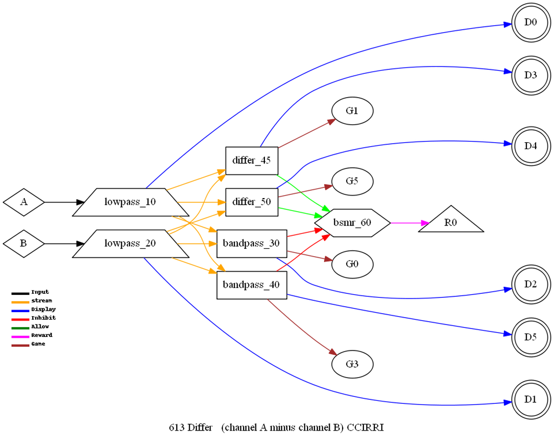
differ
Subtract the
second specified element from the first specified element, then
proceed as in OneChannelReward bandpass.
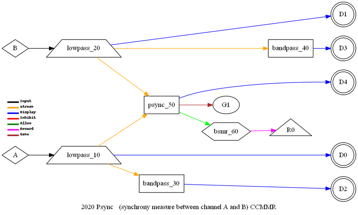
psync
Coherence measure
between peak values.
The two
(specified) input streams are each narrow-band filtered (using the
reward frequency band limits) yielding two values (x and y). A
cross correlation is then performed on a window (w) of the value
histories:
Equation
3
This reduces in
practice to
The window width
is user-specifiable but defaults to 0.5 seconds. The resulting
correlation value is smoothed using the standard EWMA filter. This
value ranges from 0 to 1. It is multiplied by a constant (user
specified but default to 10.0) to place it in an appropriate
display range (0-10) for typical EEG displays. The scaled value is
the principal output of this operation.
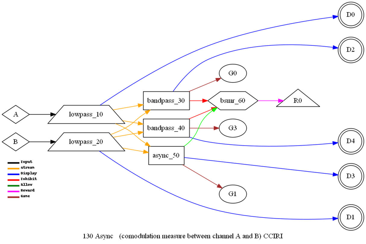
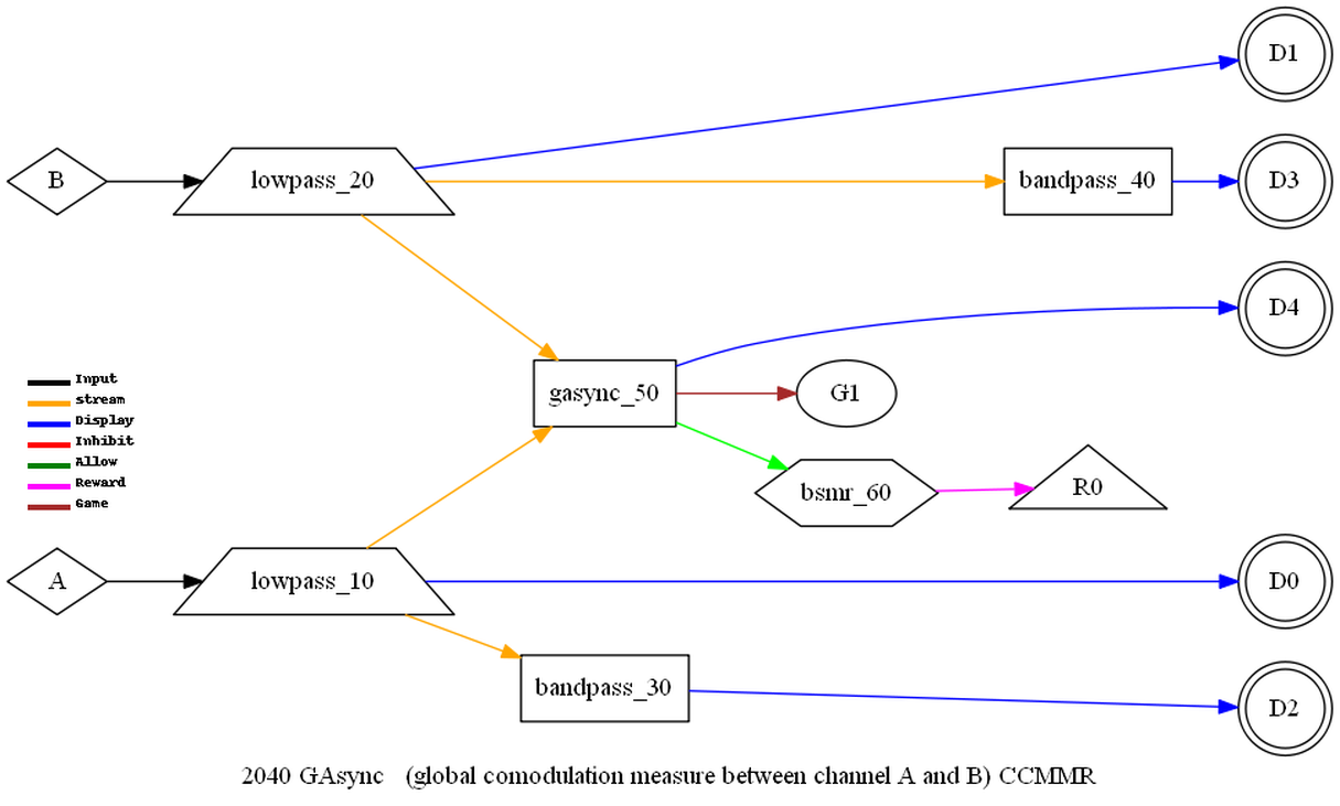
async
Coherence measure
between wave slope angles.
The two
(specified) input streams are each narrow-band filtered (using the
reward frequency band limits) yielding two values (x and y). Each
stream history is examined (looking 'backward' for one cycle) to
find the min/max of the wave. The difference between the (smoothed)
average amplitude of the stream and the current value is computed.
A cross correlation is performed of the difference values using
Equation 4. The output of this is the async value which ranges from
0 to 2. It is multiplied by a constant (user specified but default
to 10.0) to place it in an appropriate display range (0-10) for
typical EEG displays. The scaled value is the principal output of
this operation.
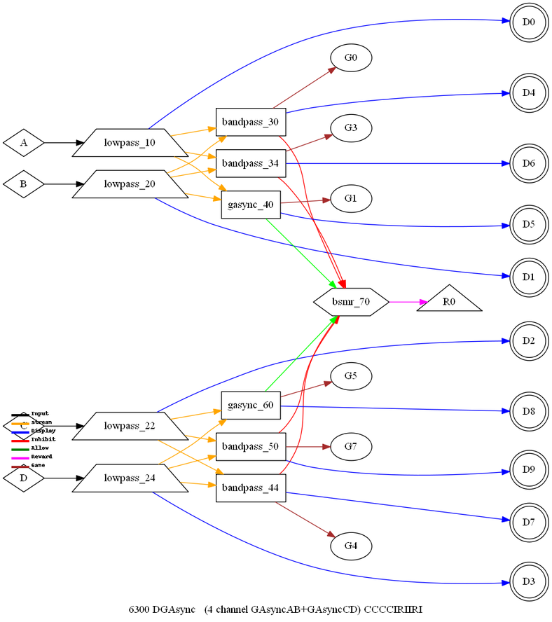
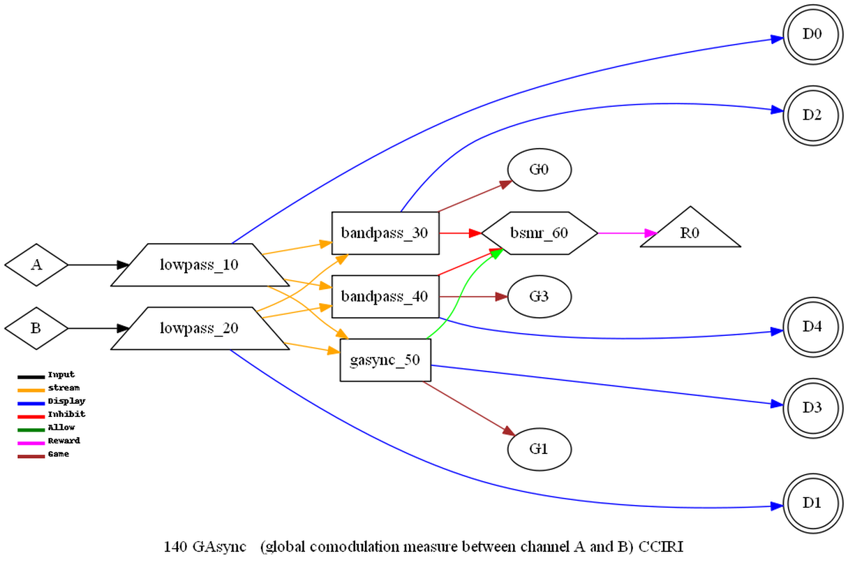
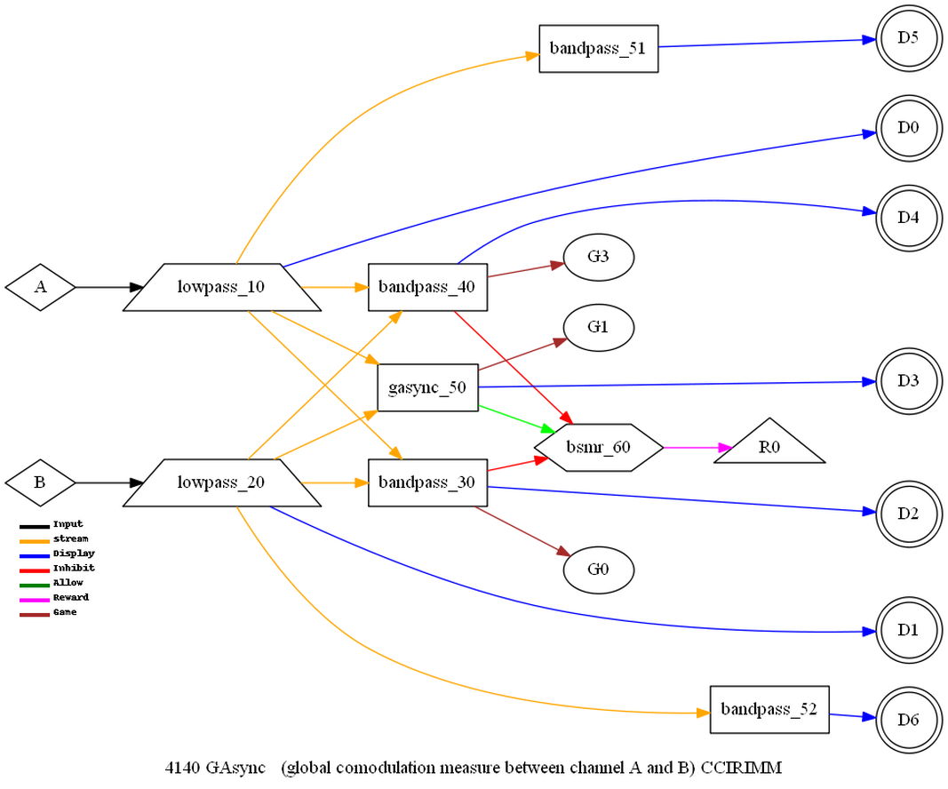
gasync
Coherence measure exactly like async except using the lowpass
(wideband) data instead of the narrow band data.
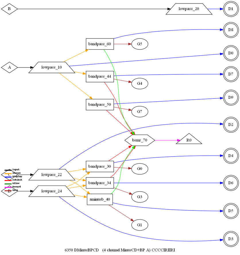
aminusb
Compute difference
between short-term average of two channels.
This operation
filters each channel of data separately and computes a short-term
moving average value. The two short-term values are subtracted and
the result added to the threshold value to give an output (display)
value.
pdelta
Compute variation in timing between peaks on two channels.
This
routine determines the 'time' of the peak value of the last cycle's
samples in each channels. The smoothed time is compared to the
smoothed time of the other channels and a normalized delta time
value is determined. The delta time is smoothed and compared to the
instantaneous delta time and used as the output value. The value is
subtracted from 1 so that zero variation in peak times results in a
perfect correlation factor. It is multiplied by a constant (user
specified but default to 10.0) to place it in an appropriate
display range (0-10) for typical EEG displays. The scaled value is
the principal output of this operation.
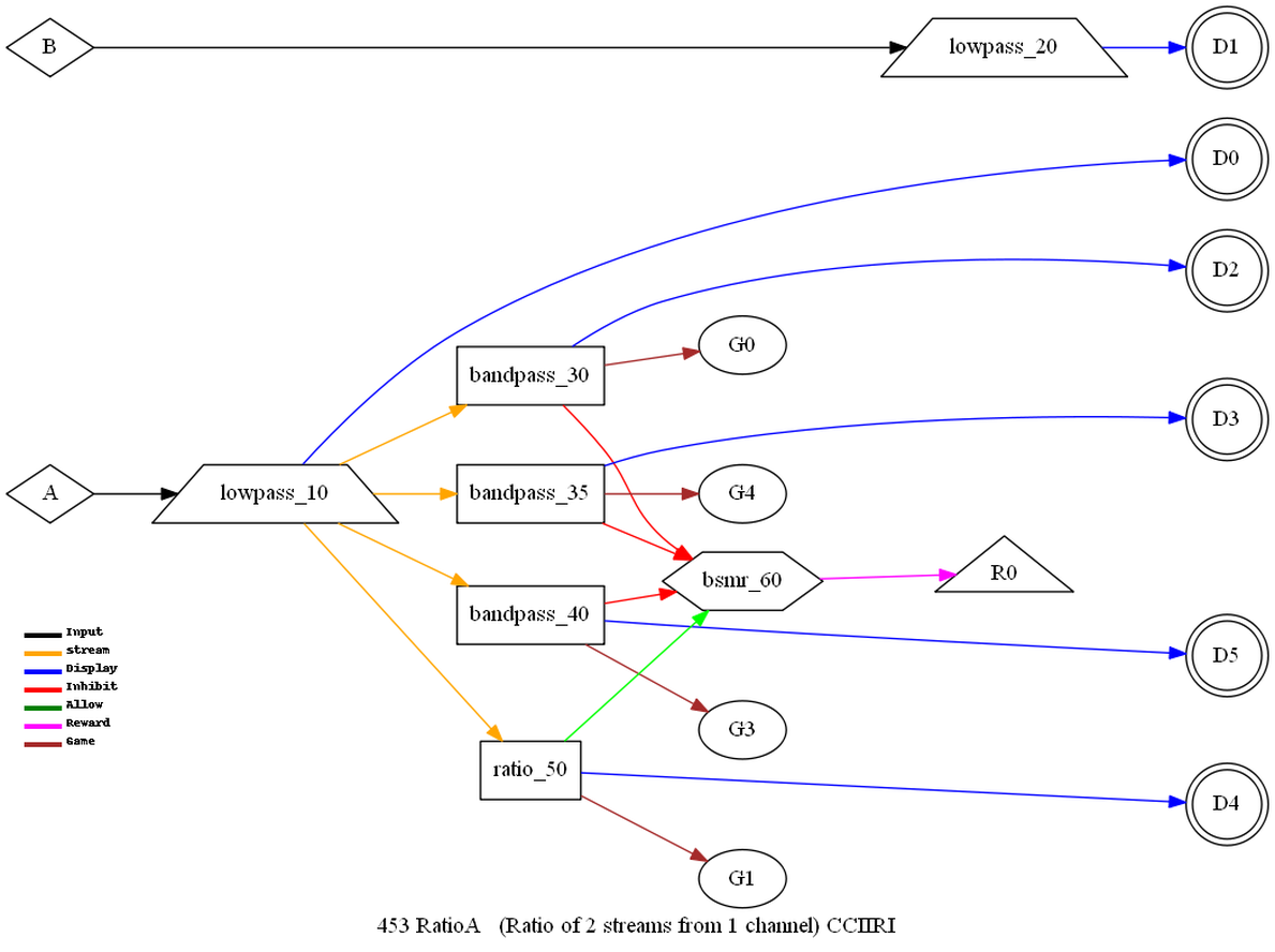
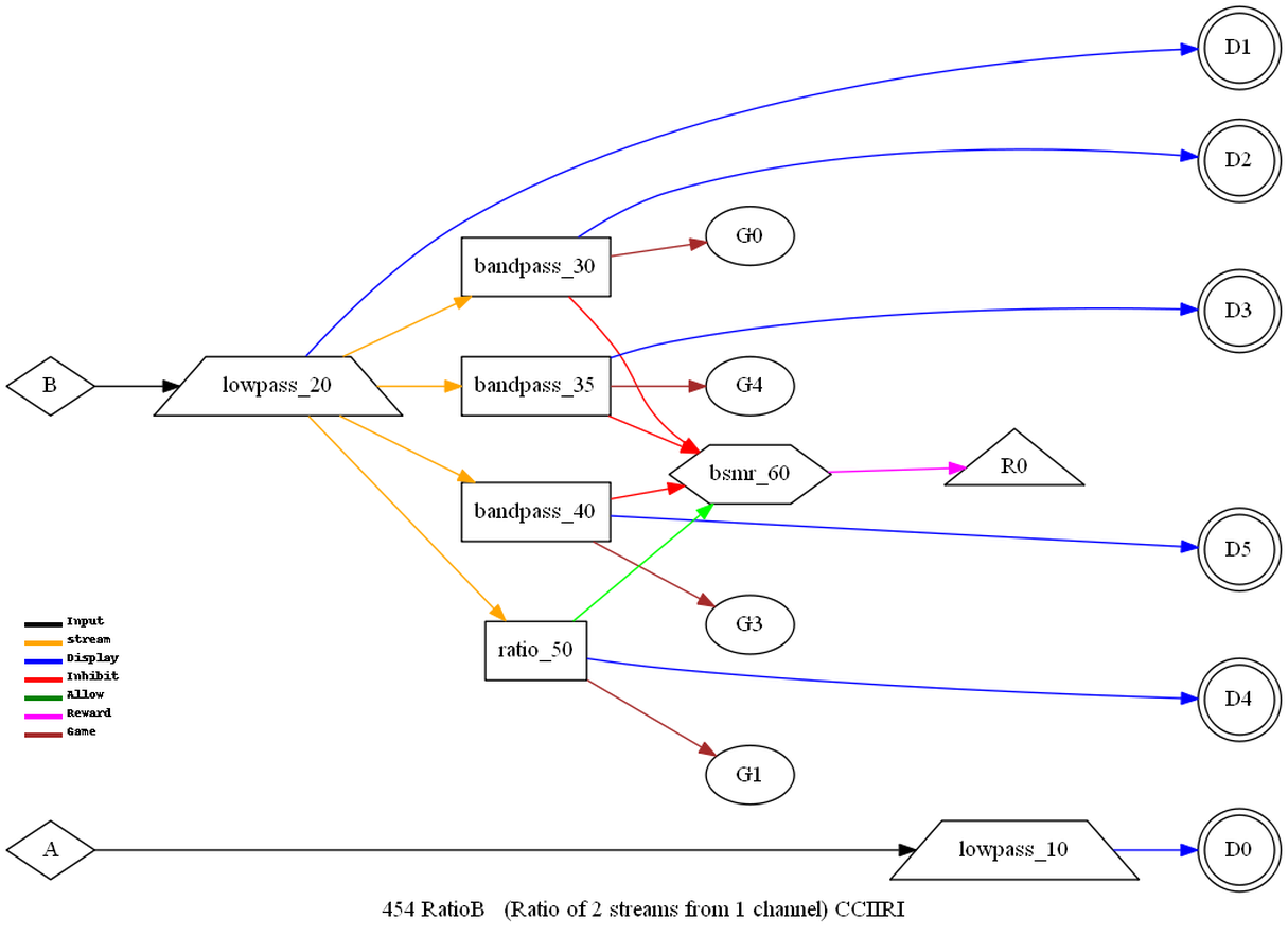
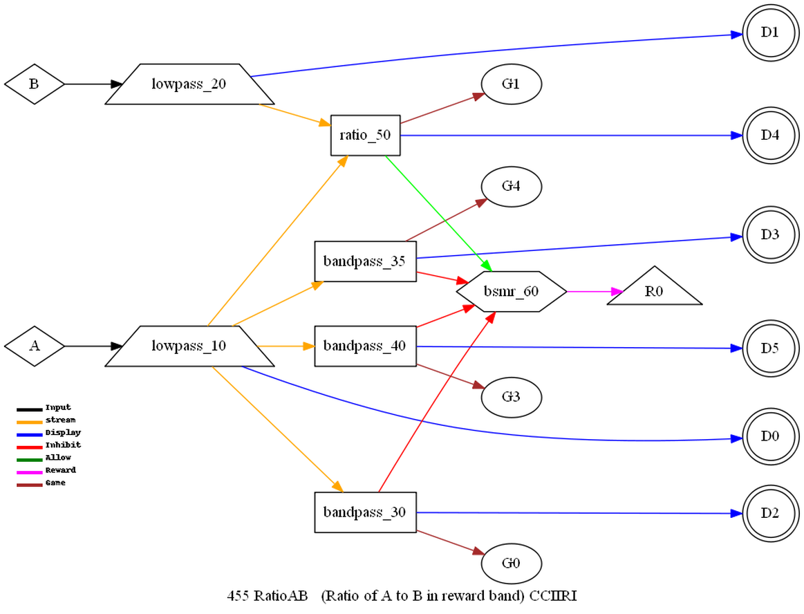
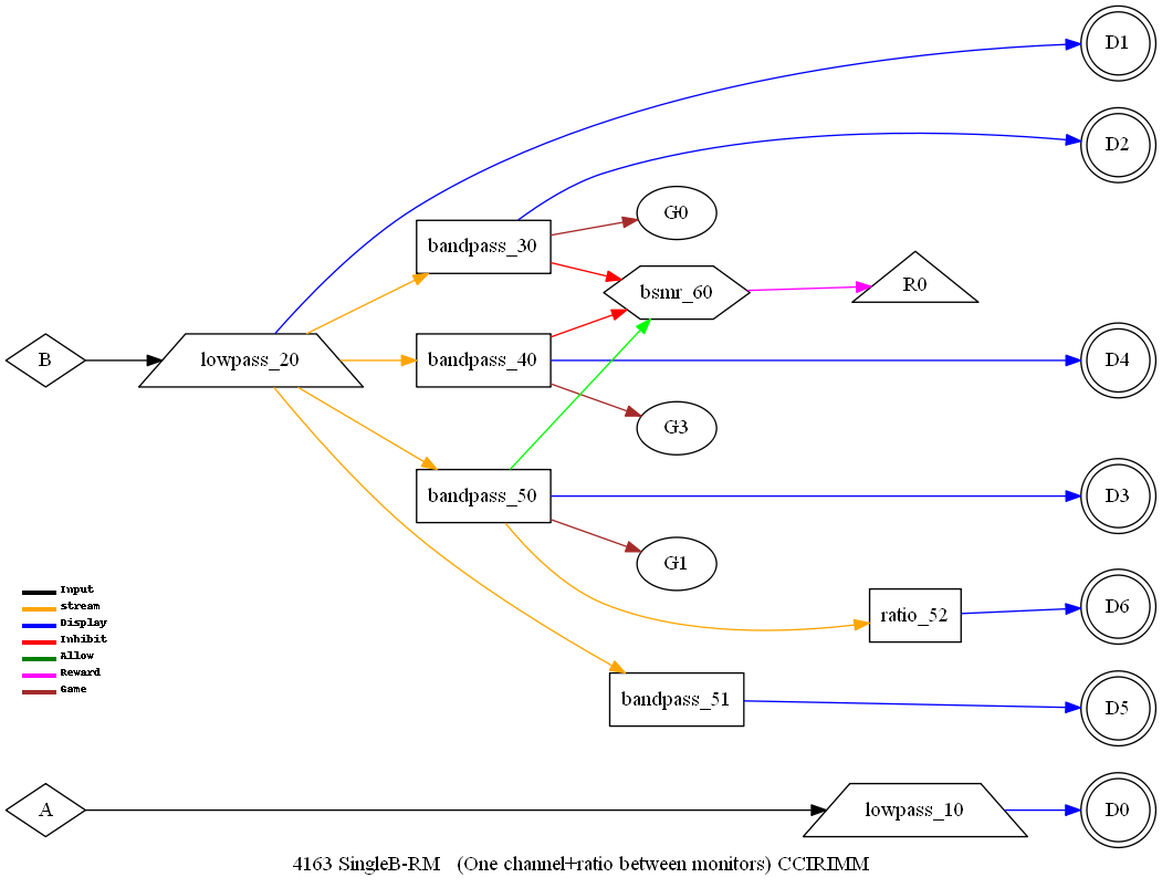
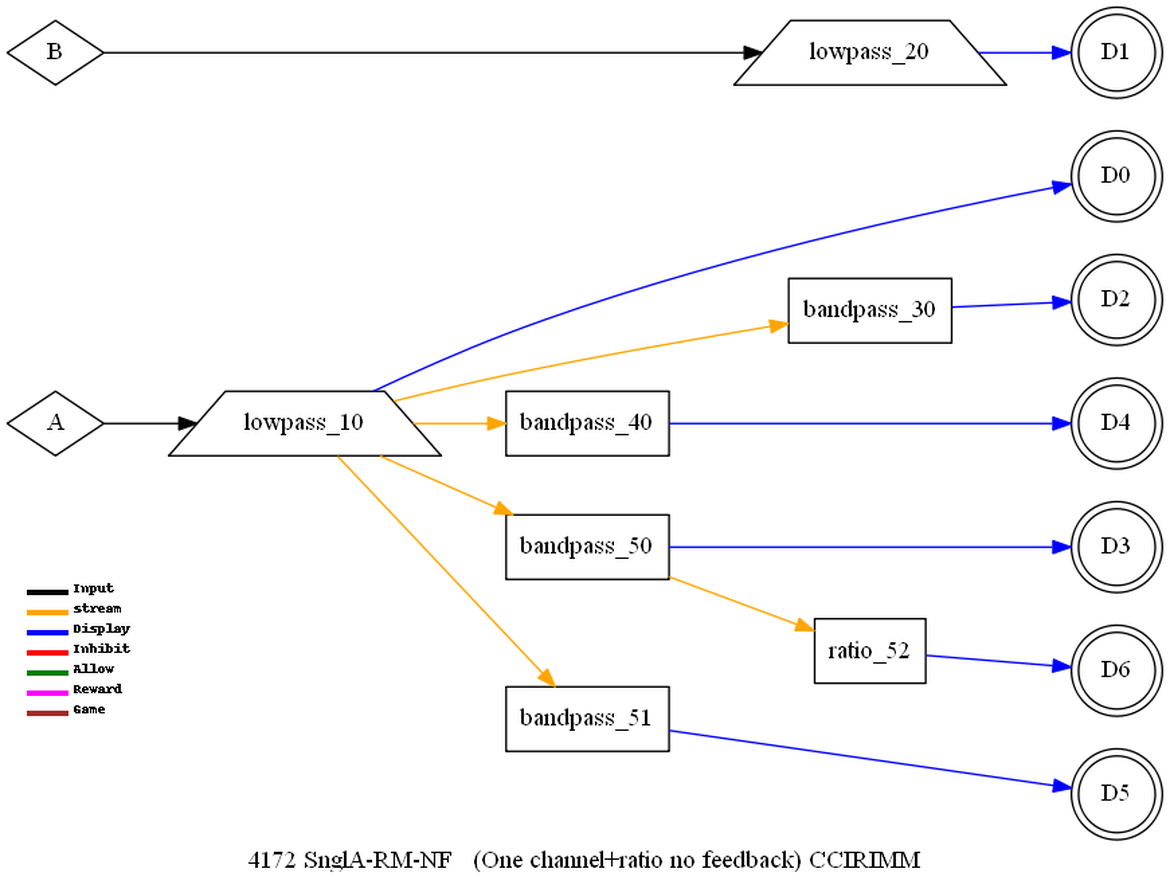
ratio
Compute the ratio of two channels or two streams of data.
Depending in the input specifications, this operation determine the
ratio of the inputs. It is a user configuration selection whether
the ratio is squared (for power) or not (for voltage).
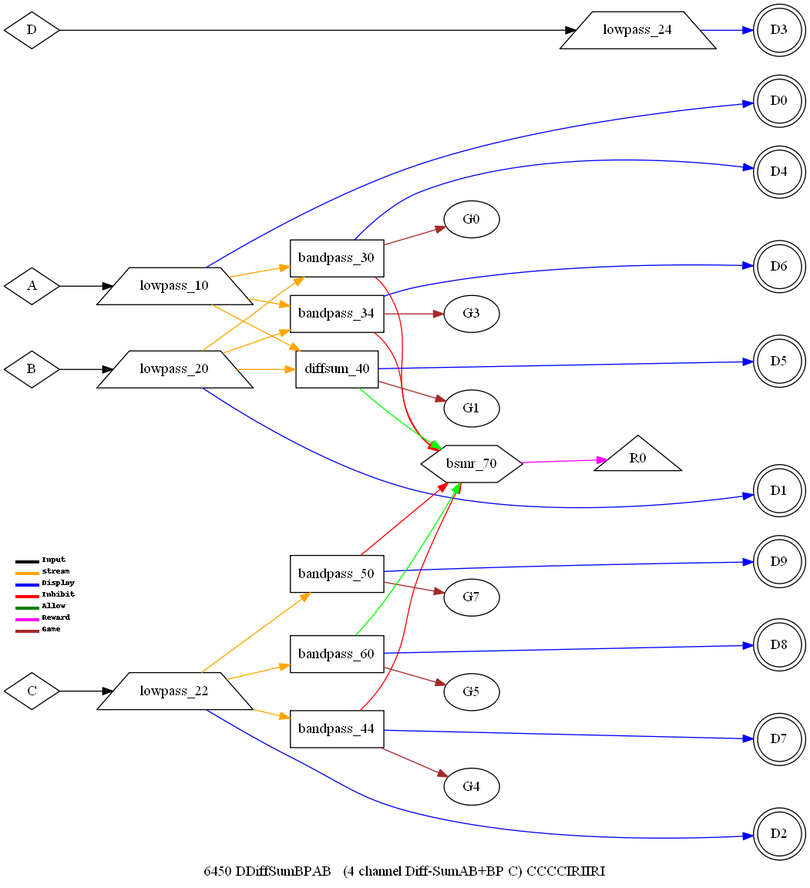
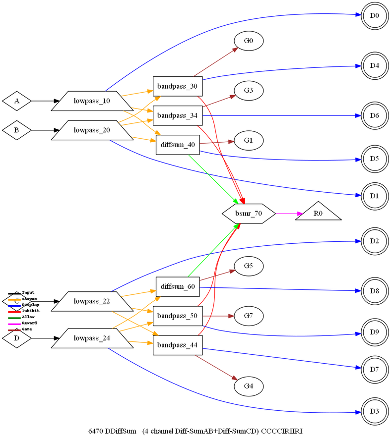
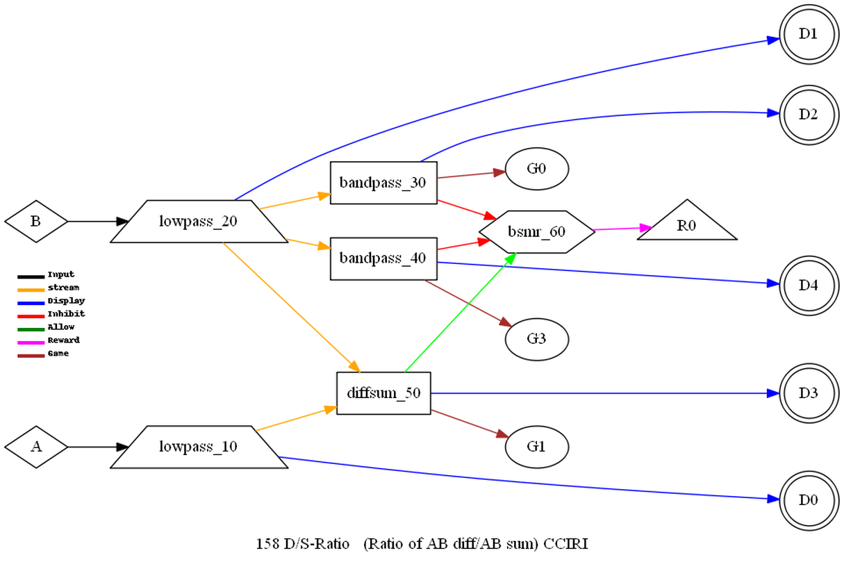
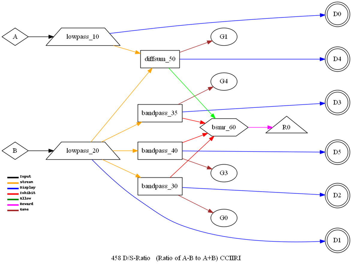
diffsum
This
operation computes the difference of the filtered samples divided
by the sum.

Equation
5
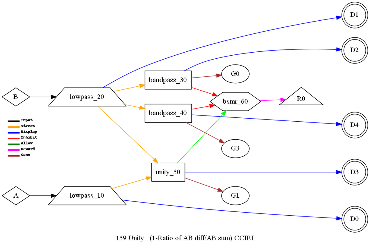
unity
This
operation is very similar to the diffsum operation except the value
is subtracted from 1.
Equation
6
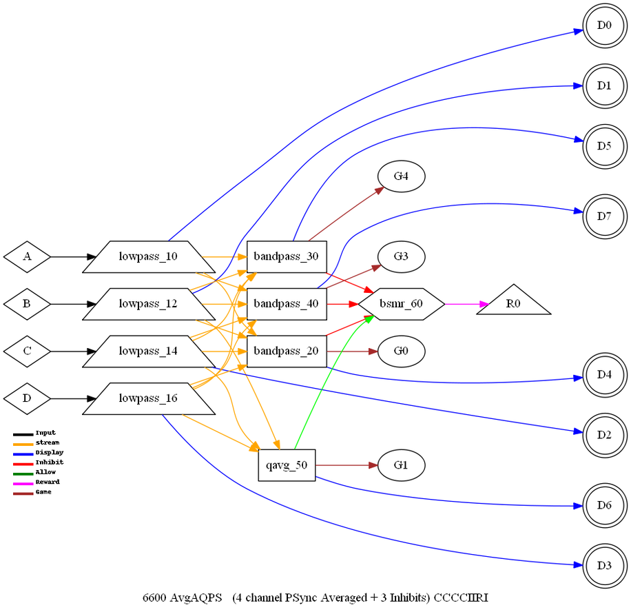
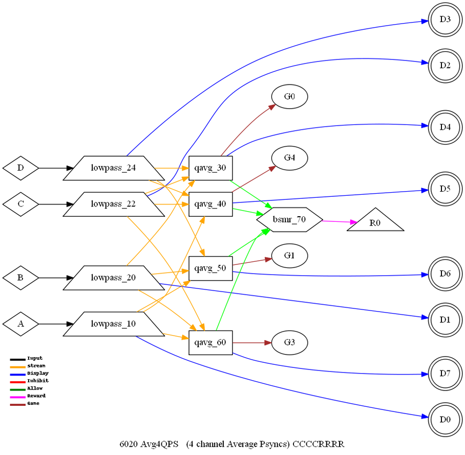
QPS
modes
The
QPS modes are 4-channel modes where the coherence of each pair of
bands is computed/averaged to improve hypo- or hyper-coherence.
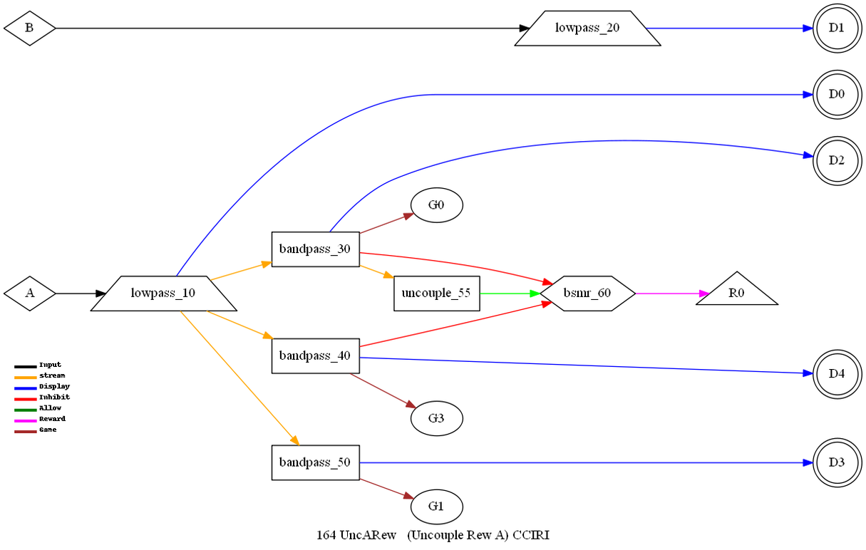
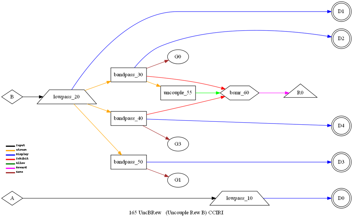
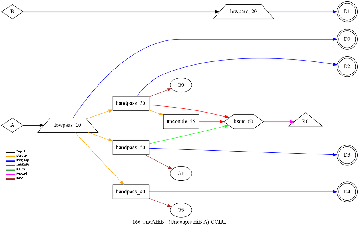
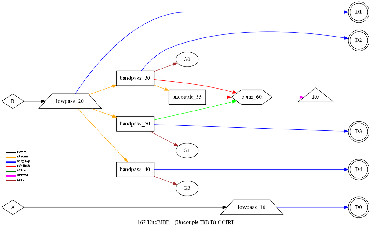
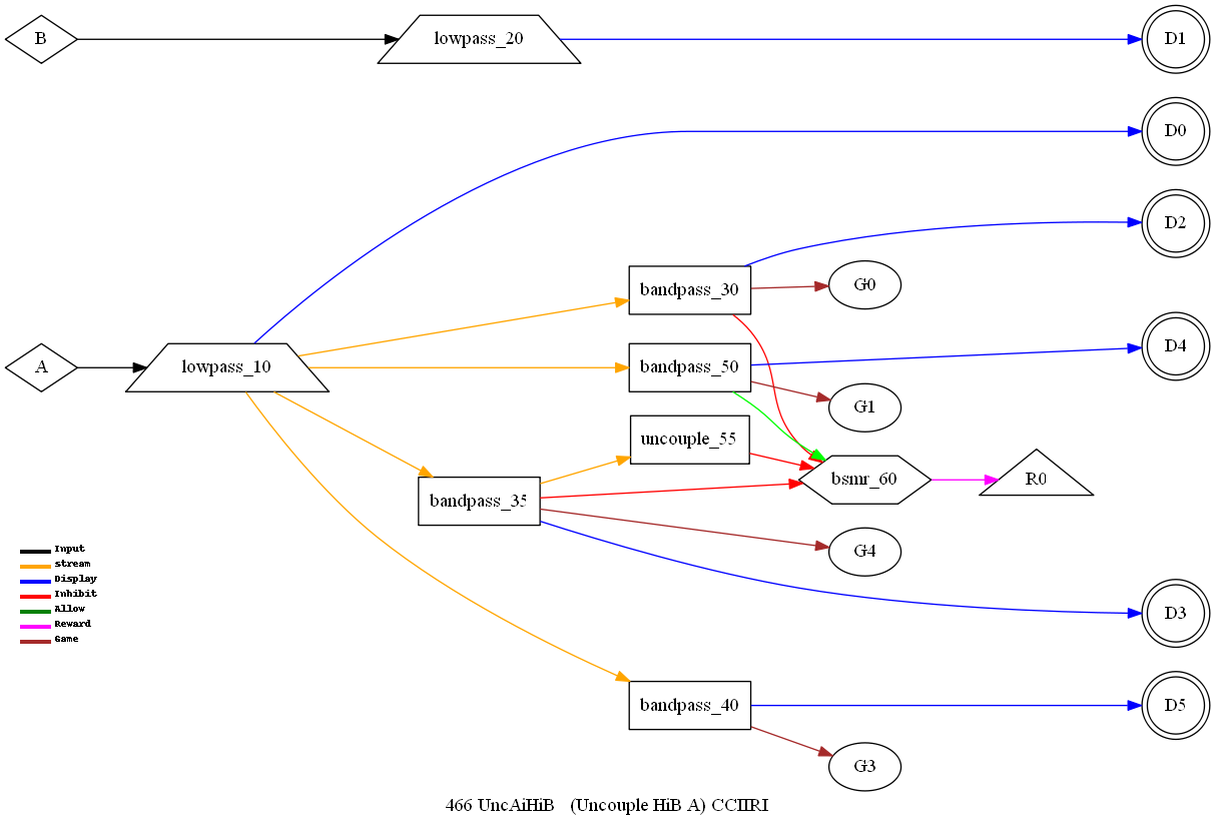
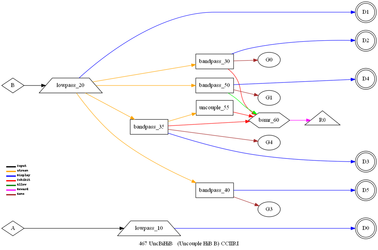
uncouple
This
operation monitors (typically) a low frequency band for a spindle
exceeding a (user) threshold. When seen, it alters (temporarily)
the threshold for (typically) the reward band. The purpose of these
modes is to inhibit rewards when spindles are detected in the
monitored band.
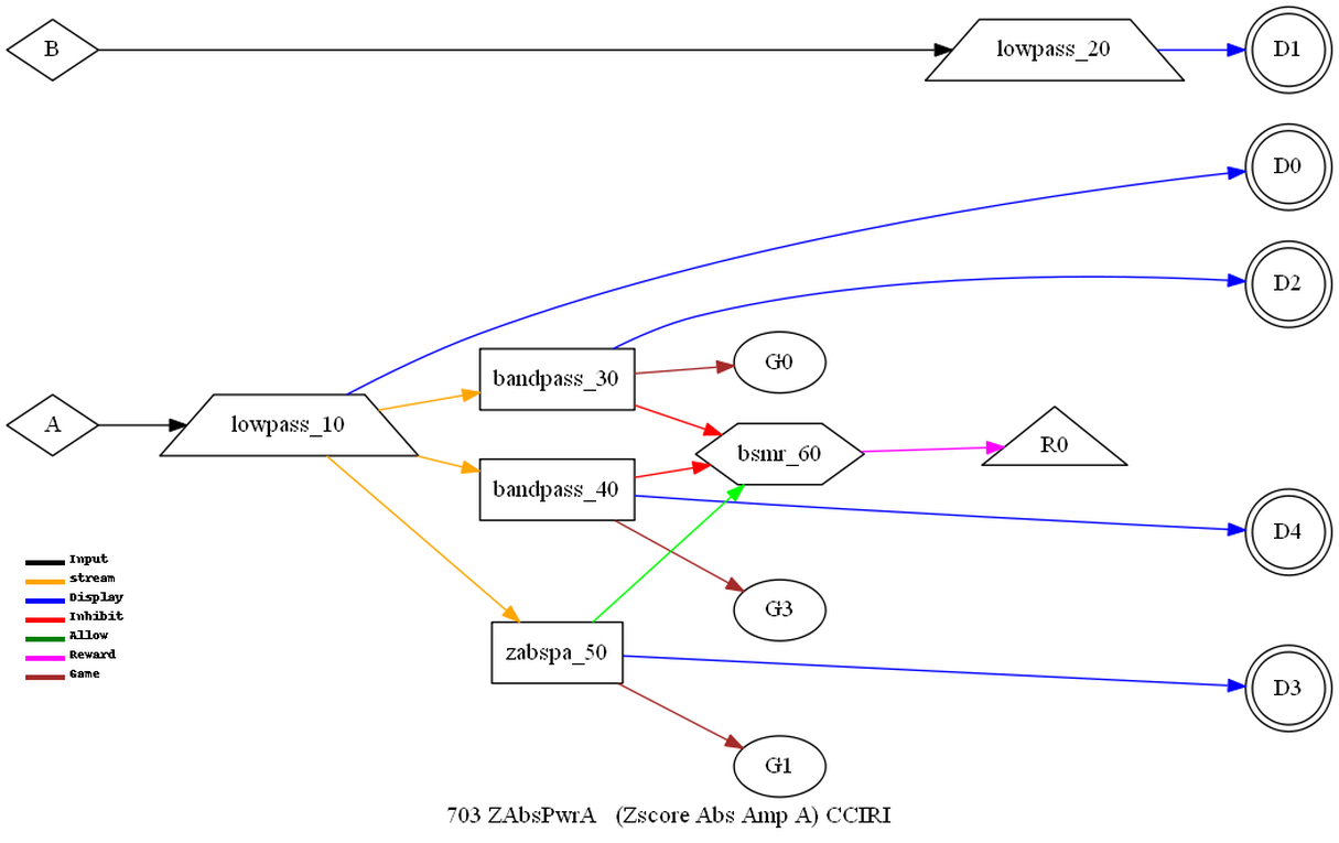
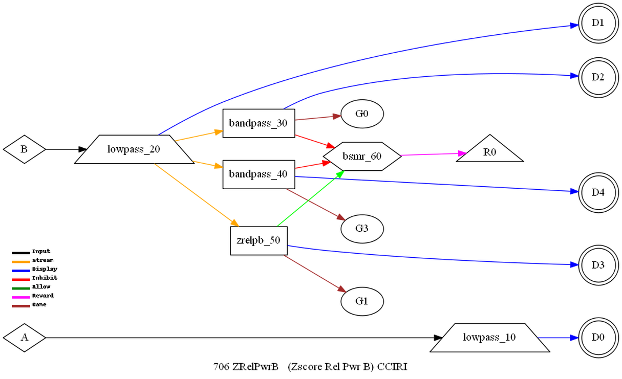
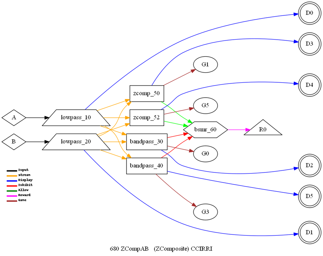
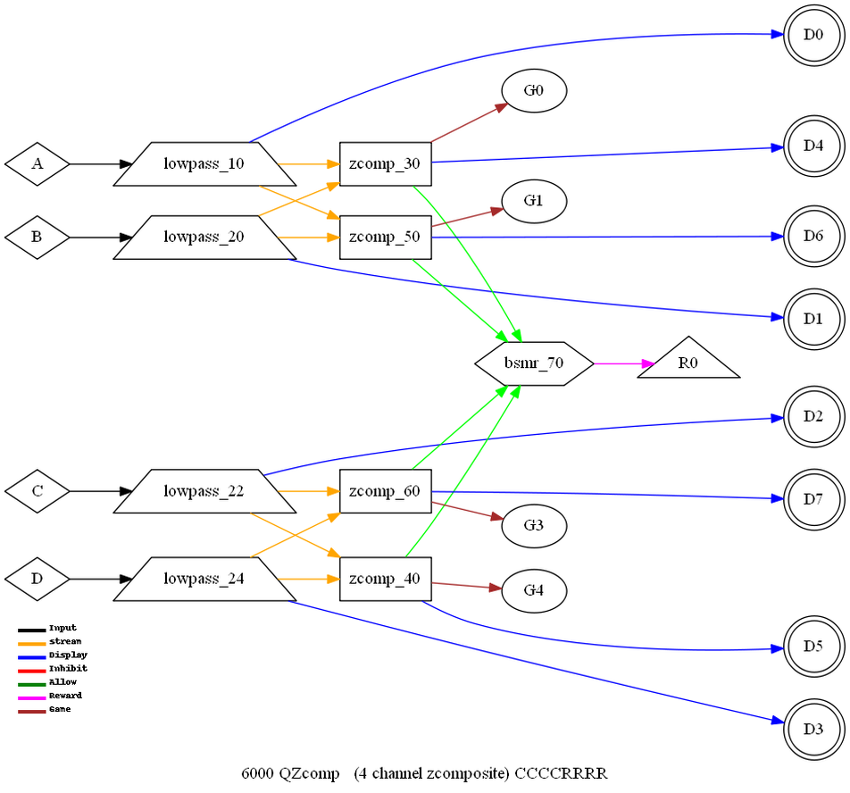
zcomp
This operation is
not a filtering operation but examines various output combinations
of data computed by the Applied NeuroScience Inc. (ANI) zscore
module. The zcomp logic examines each user-specified element of the
ANI data outputs and tracks the percentage of rewardable states.
The composite percentage is the output of this operation block.
Further details of the comparison logic are described in the
Operator Manual.
The following
operations are not filtering operations but reward decision
operations that receive inhibit and reward inputs and make various
decisions about scoring, sounds, etc.
bsmr
This
operation block accepts the inhibit and reward threshold
comparisons and determines rewardable state for SMR and EXP
protocol classes. It also determines if a reward event is to occur
based on time-on-task, event rate, time between rewards, and other
controlling criteria.
at
This
operation block accepts the inhibit and reward threshold
comparisons and determines rewardable state for the AT protocol
class. Reward sounds are determined in the feedback games/displays.
The feedback consists of two
environmental tones signaling the general range of the client's state-of-relaxation, and tones
that signal momentary bursts of EEG in one or the other reward
band. The alpha environment is a running stream, and its tone is a
high-pitched bell. The theta environment is ocean waves, and the
theta tone is a low-pitched bell. As relaxation deepens, the
ongoing environmental sound will cross-fade from stream to ocean
and low-pitched bell tones will replace the high-pitched tones. In
cases where both frequency ranges are over threshold at the same
time, the system is biased toward signaling the alpha state. The user has control over the “fade” rate when
transitioning between states. If neither signal is over threshold,
there will be no change in relative volumes (fading).
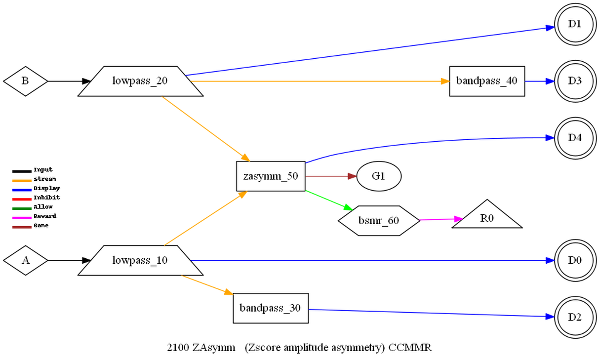
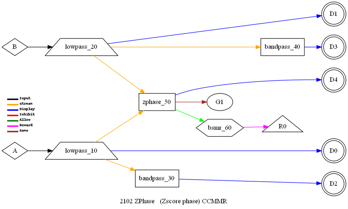
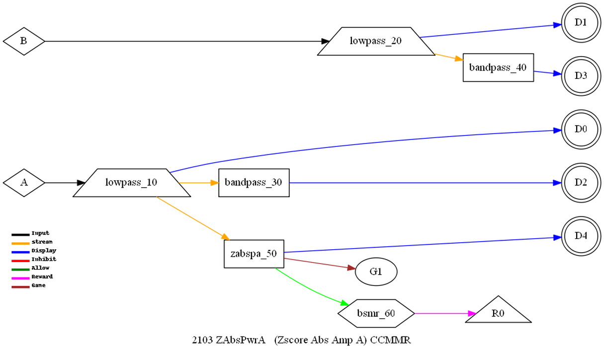
The following
operations are not strictly operations performed by EEGer4. They
consist of various selection of outputs from the Applied
NeuroScience Inc. (ANI) zscore module for display/reward
controls.
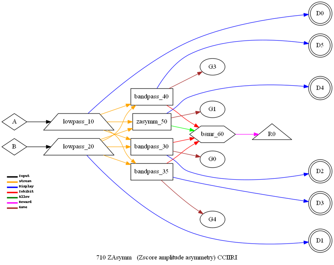
zasymm -
asymmetry measure
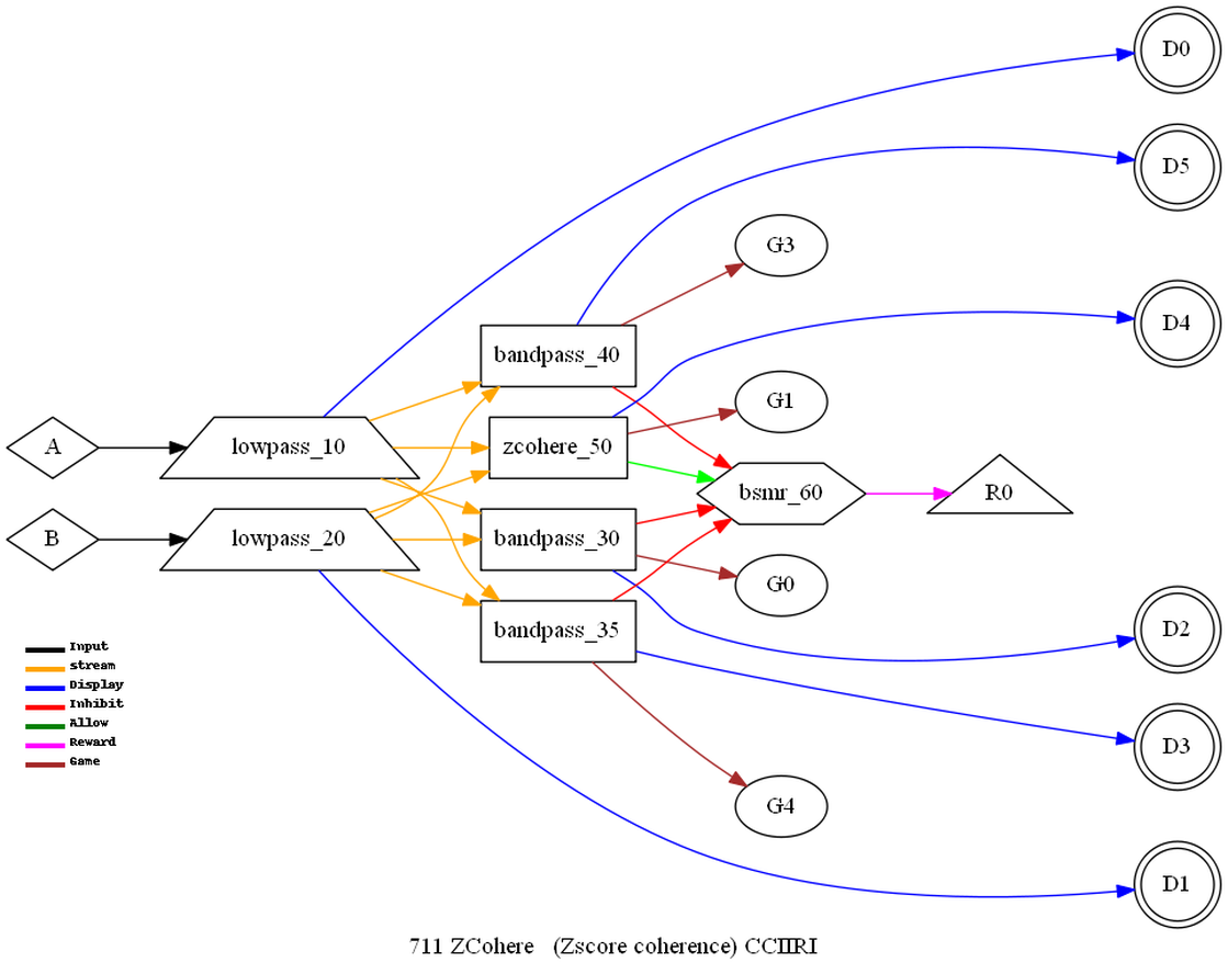
zcohere -
coherence measure
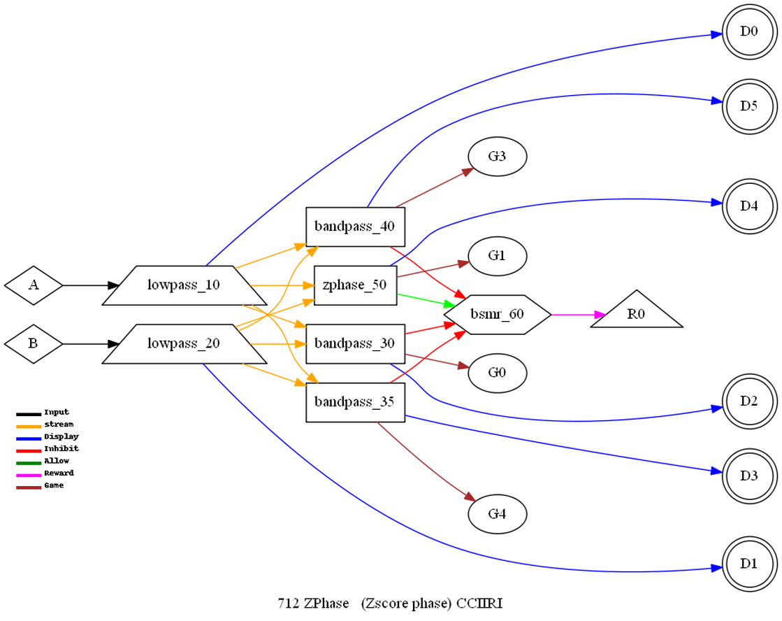
zphase -
absolute phase measure
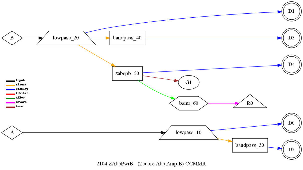
zabspa -
absolute power
zabspb -
absolute power
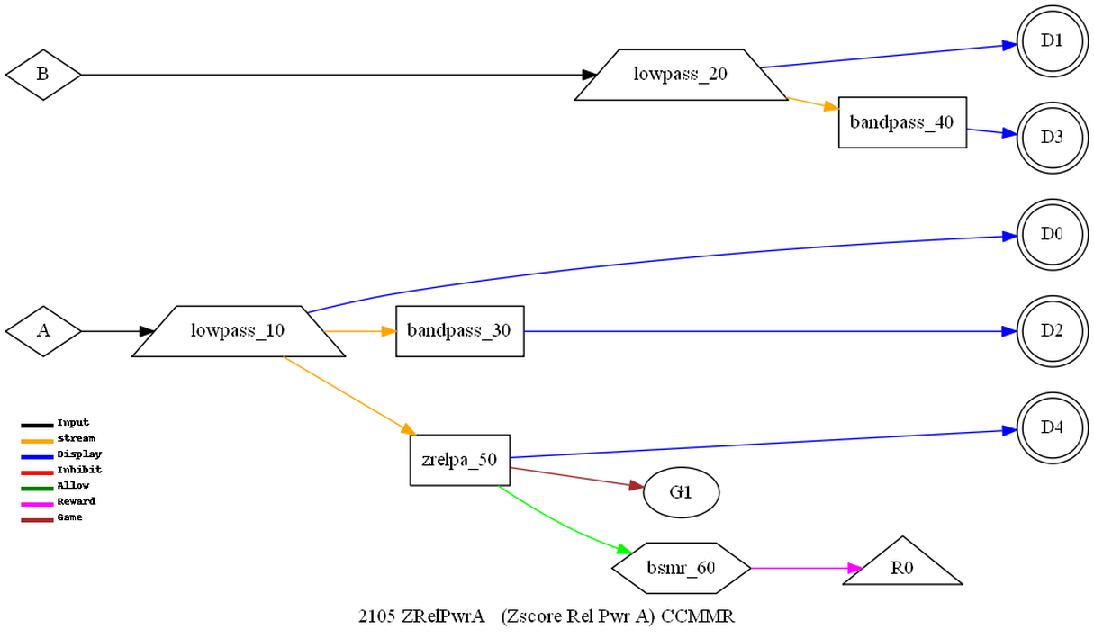
zrelpa -
relative power
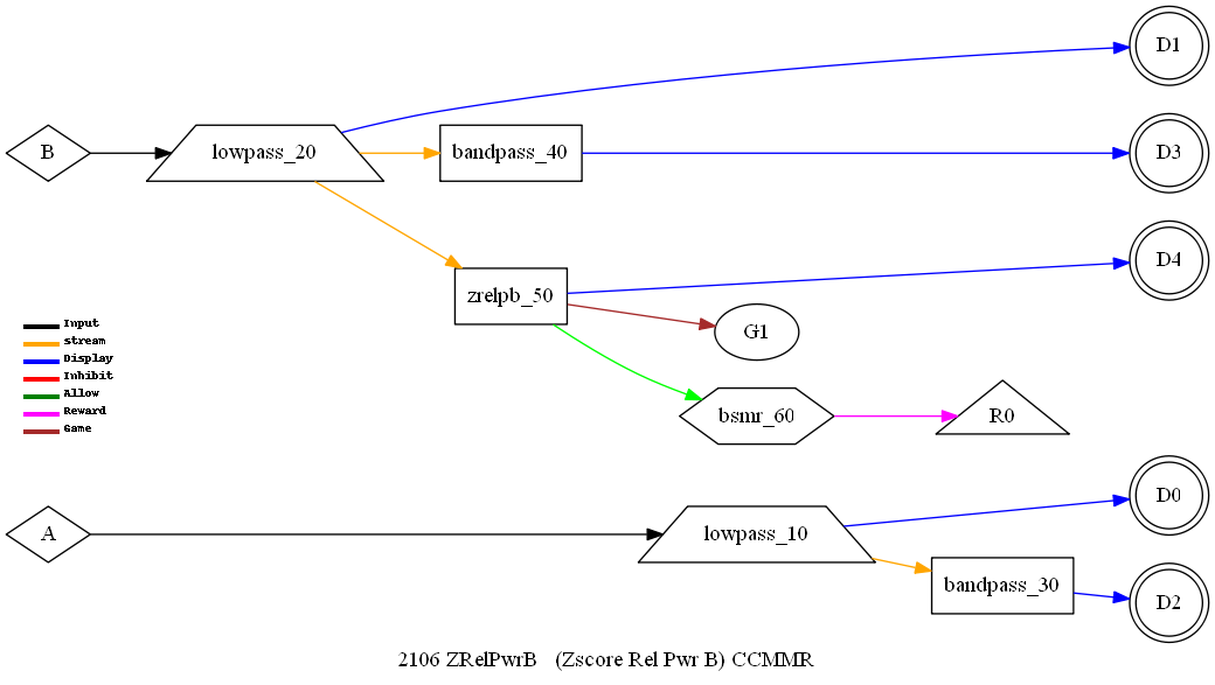
zrelpb -
relative power
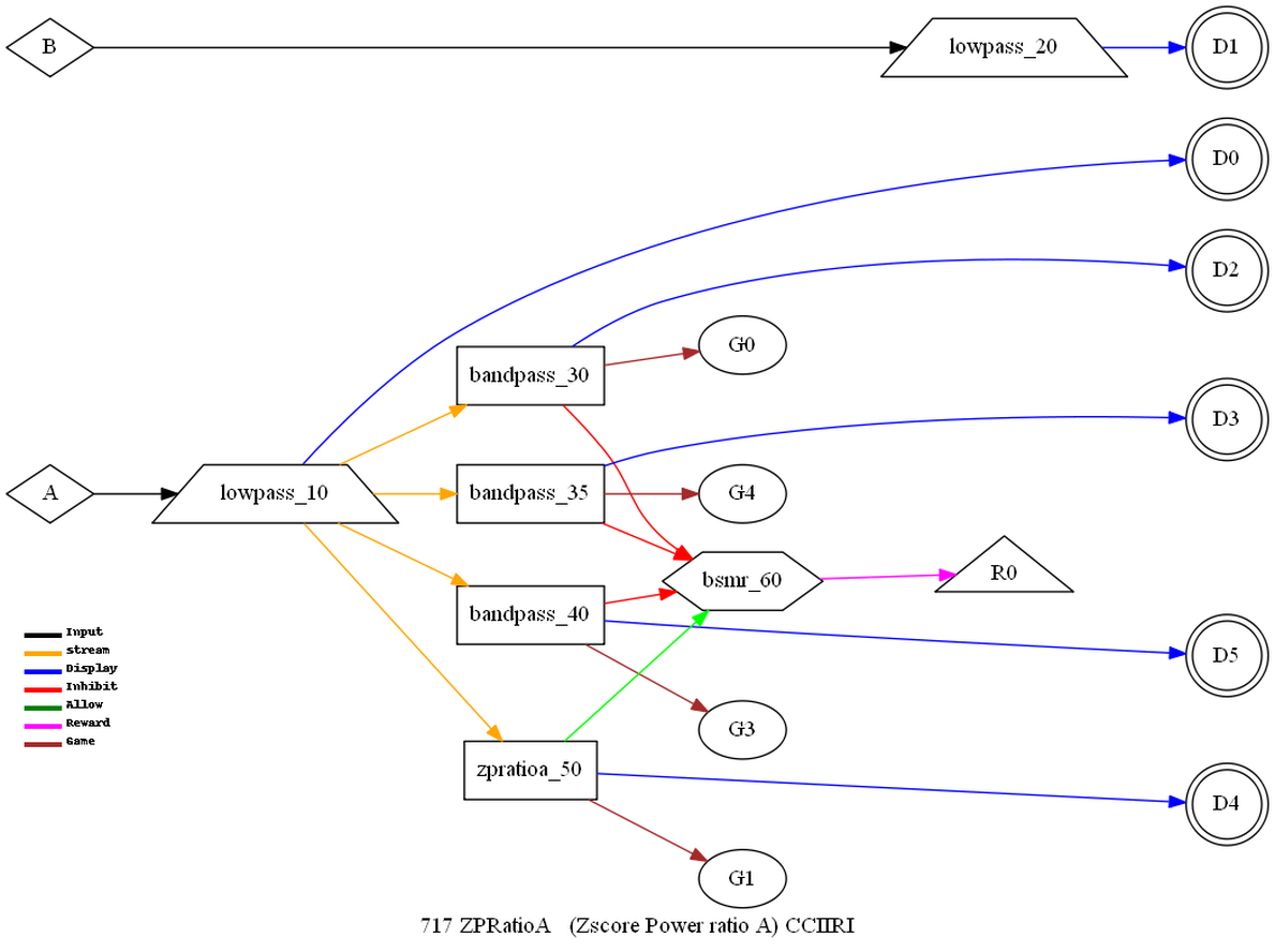
zpratioa –
power ratios
zpratiob –
power ratios
For an
explanation of these computations, please see the applicable ANI
documentation.
All the feedback
modes are diagrammed in Appendix C.
Examples of modes
Some explanation
of (internal) entries in the samples below:
display
means display the output
game
specifies the game strand
extra
enables multiple reward modes
proc gives
text displayed to therapist
kind is the
layout code where C means channel, I means Inhibit, R means
reward.
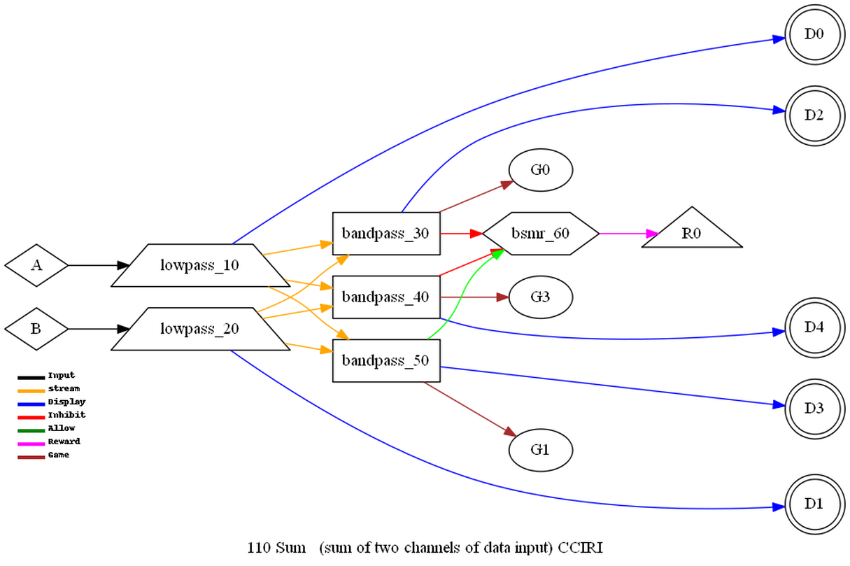
Each stream has
its own frequency bandwidth for bandpass filtering.
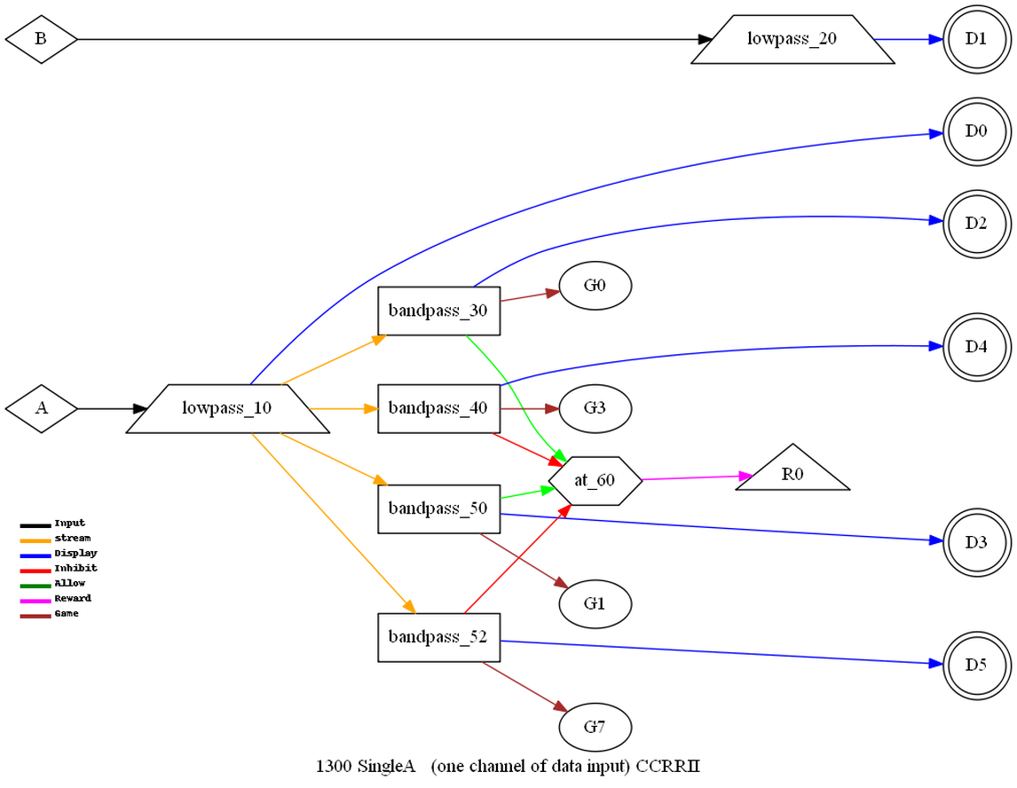
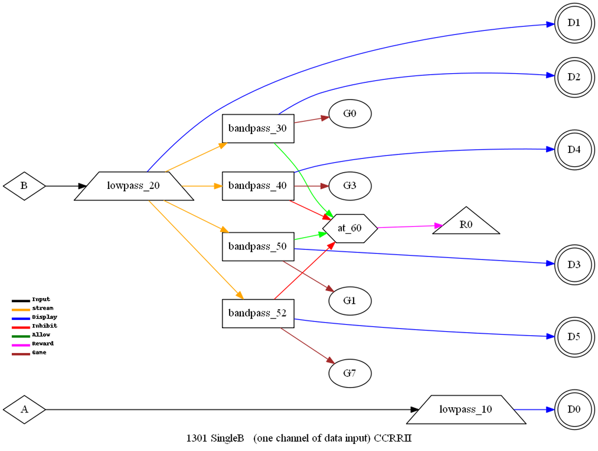
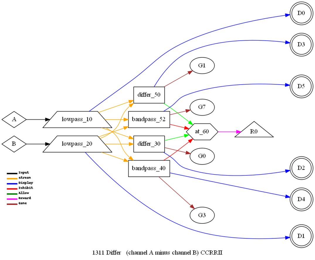
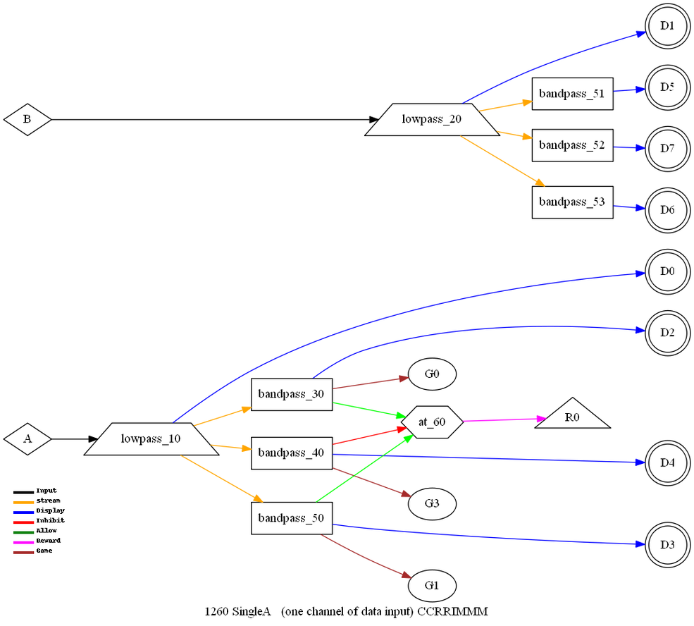
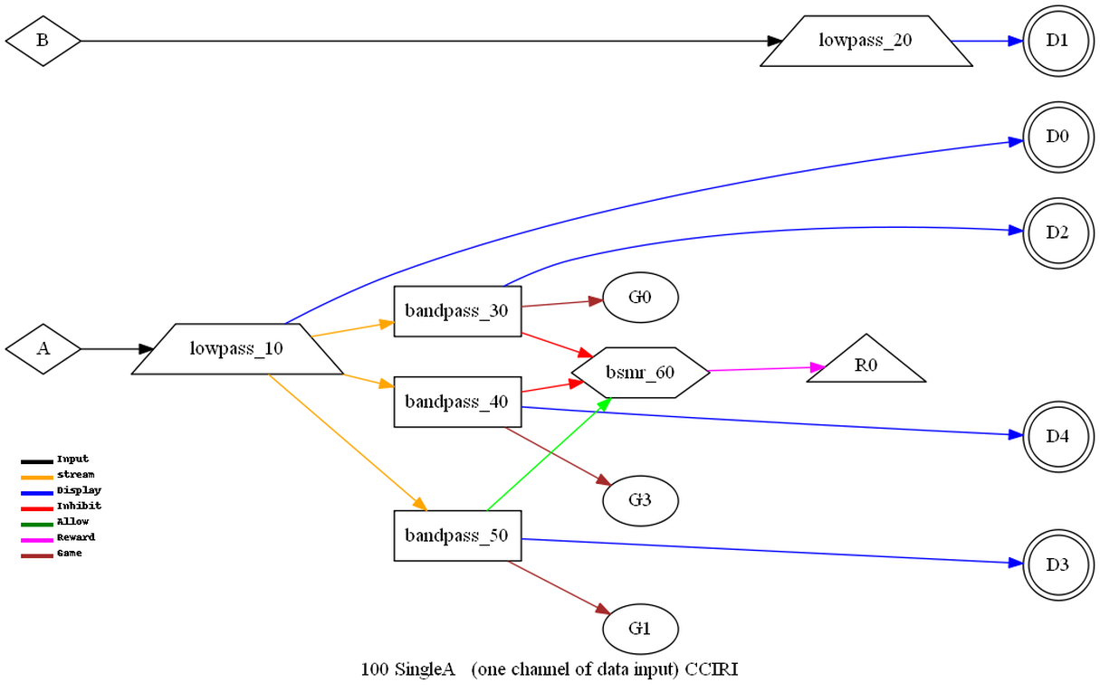
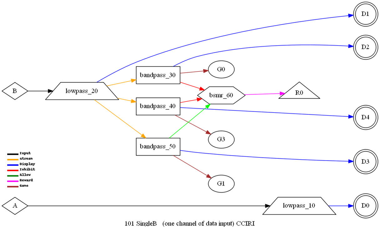
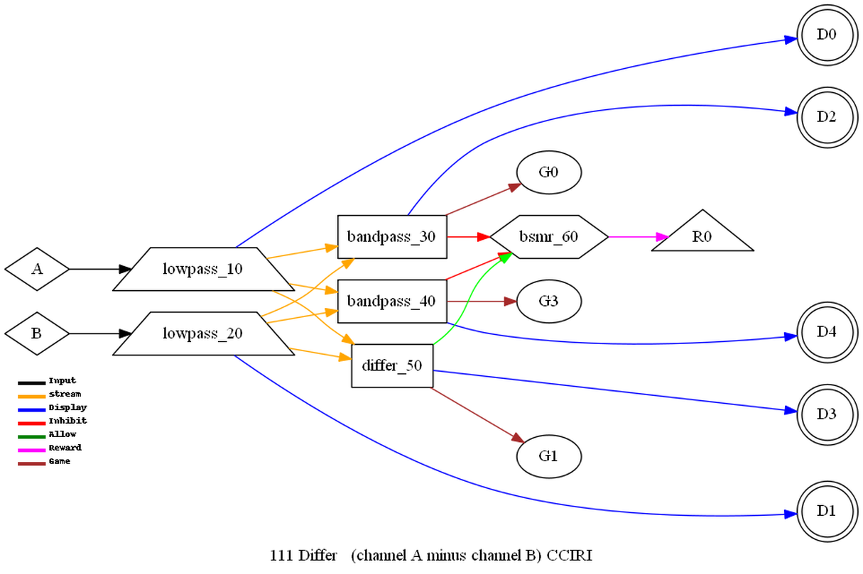
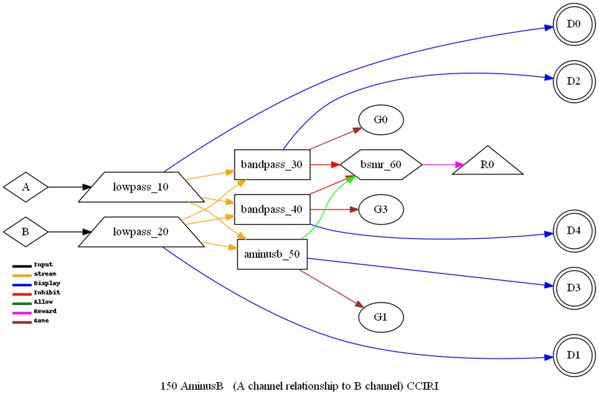
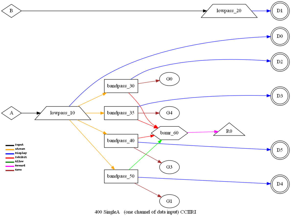
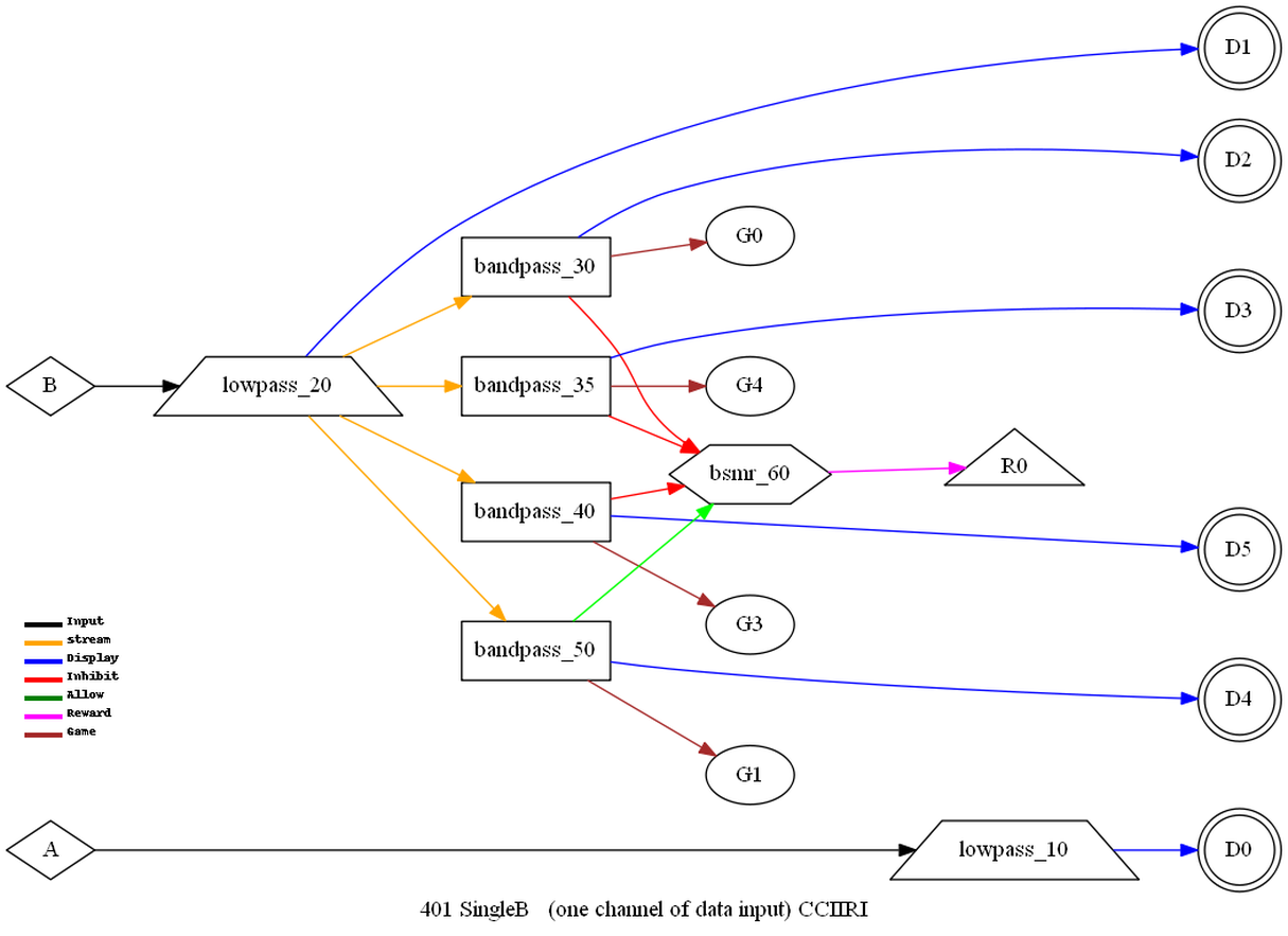
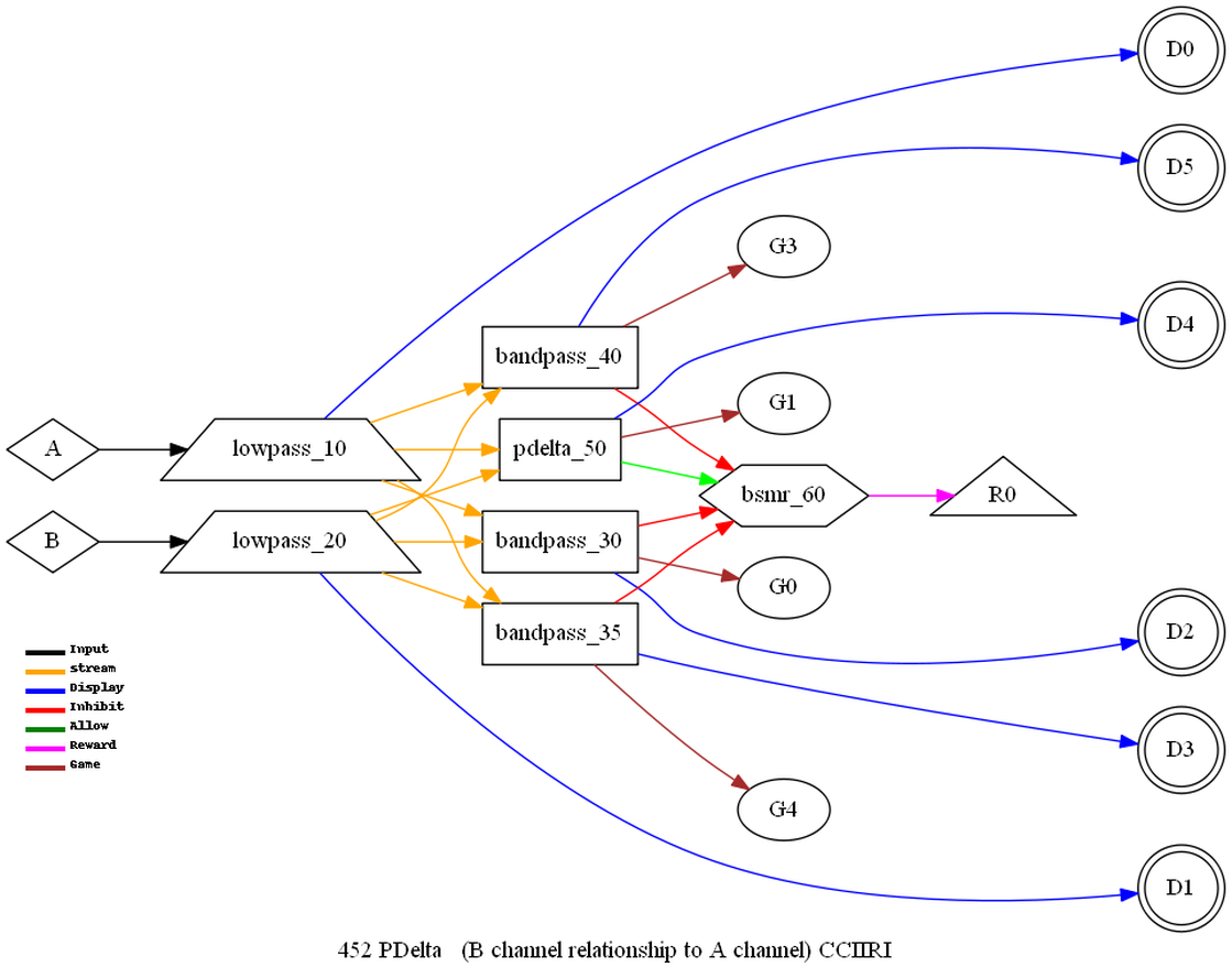
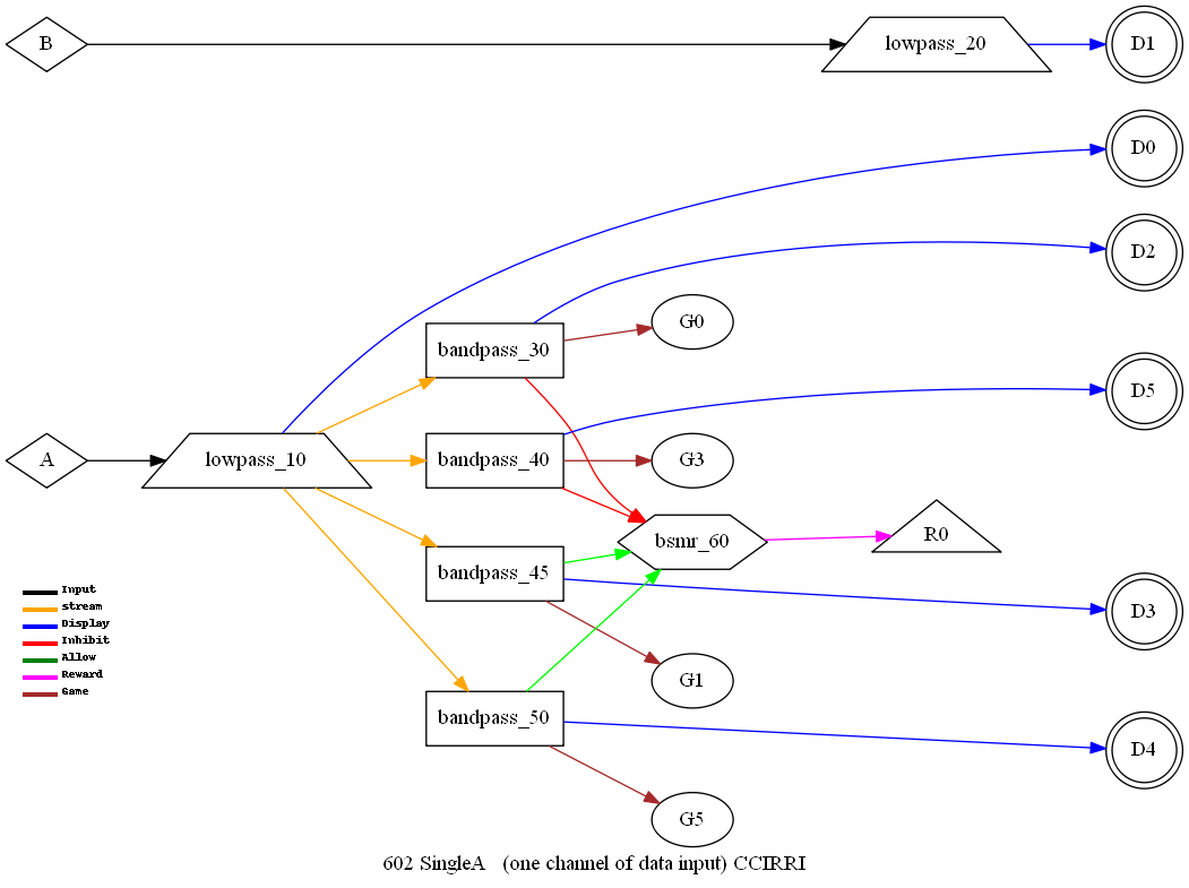
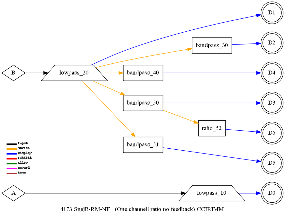
A simple example
of the mode logic (all diagrammed in Appendix C) is Differ.
kind=CCIRI
10=lowpass,in=0,out=0,display >Lowpass channel A, display
on trace 0
20=lowpass,in=1,out=1,display >Lowpass channel B, display
on trace 1
30=bandpass,in=0-1,out=2,game=0,display >Bandpass trace 0 and
1
added, display on
trace 2
40=bandpass,in=0-1,out=4,game=3,display >Bandpass trace 0 and
1
added, display on
trace 4
50=differ,in=0-1,out=3,game=1,display,extra,proc=Diff >Subtract
trace 1 from trace 0,
bandpass, display
on trace 3
60=bsmr,in=3-3,inhibit=2-4 >Reward if trace 3 rewardable
and no inhibit on
traces 2
and 4
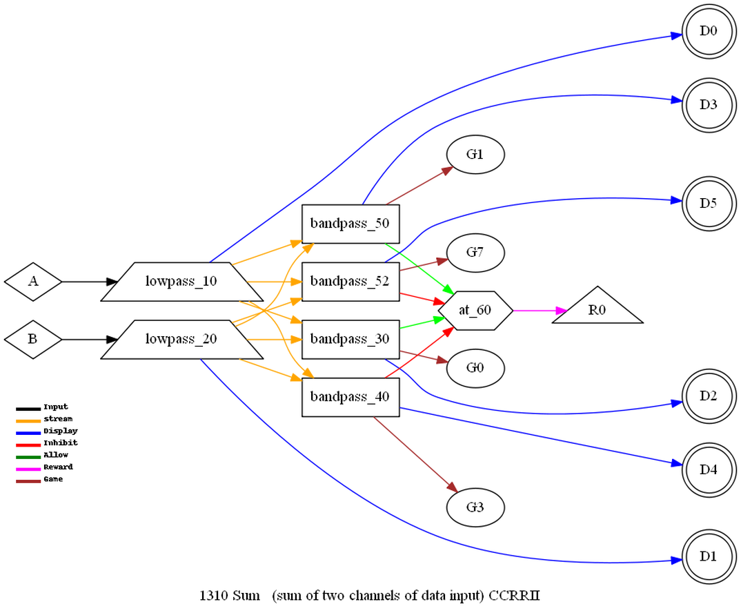
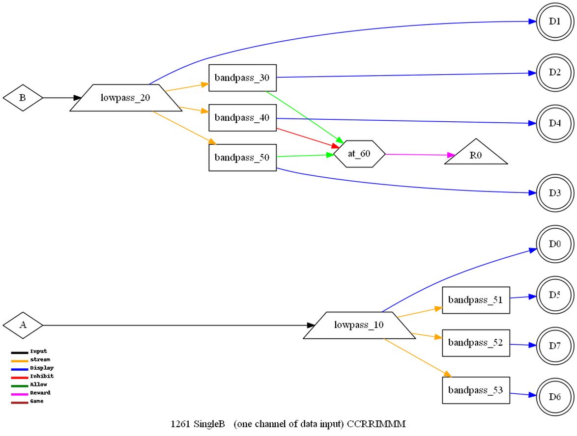
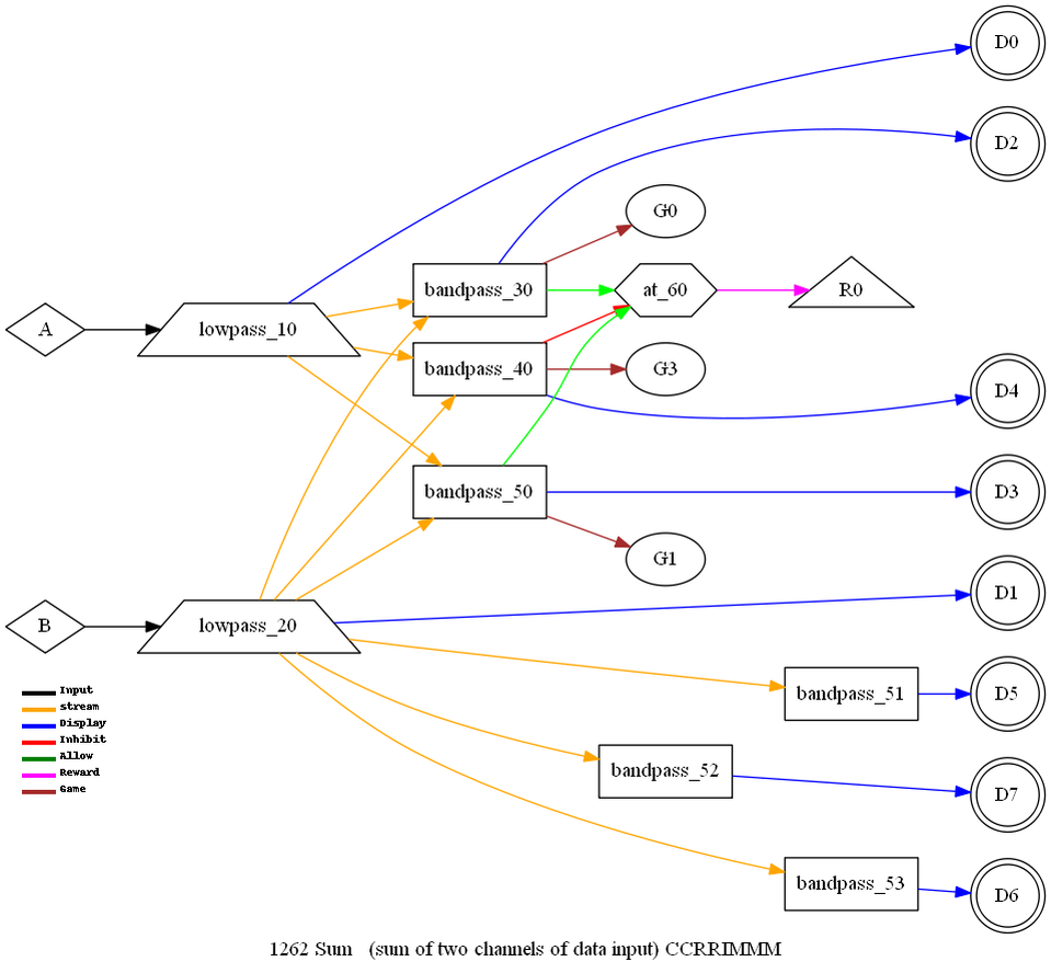
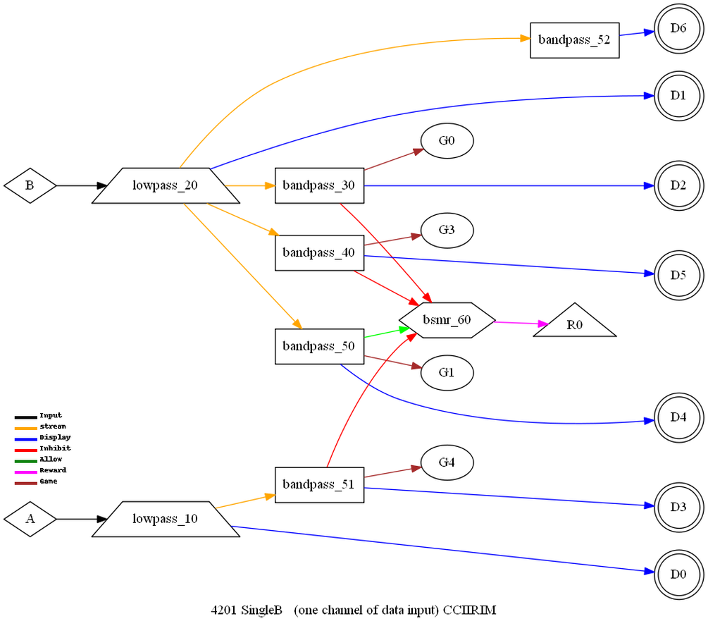
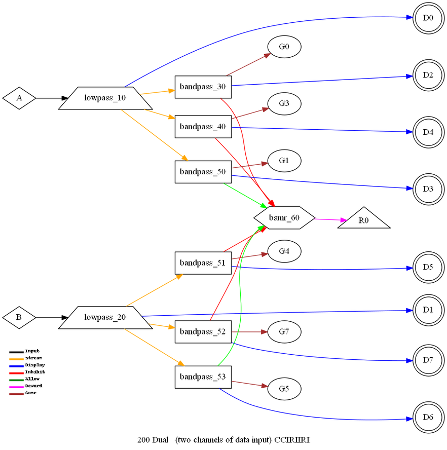
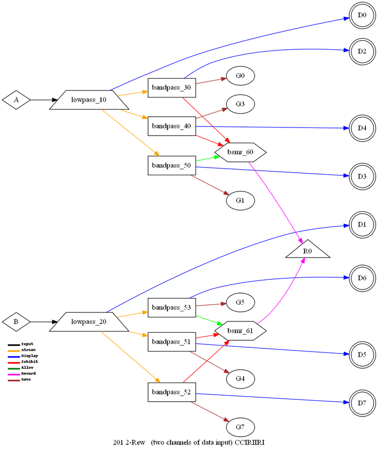
Another example is
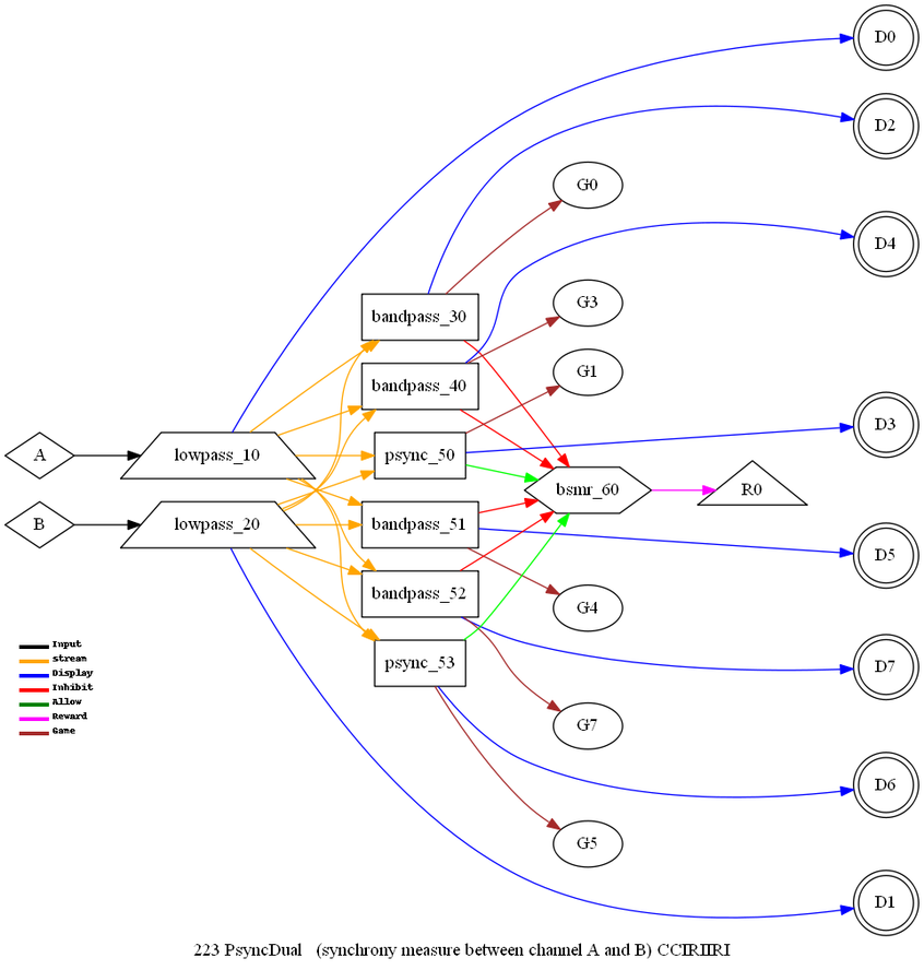
the 8-trace Dual mode:
kind=CCIRIIRI
10=lowpass,in=0,out=0,display
20=lowpass,in=1,out=1,display
30=bandpass,in=0,out=2,game=0,display
40=bandpass,in=0,out=4,game=3,display
50=bandpass,in=0,out=3,game=1,display,extra,proc=Ampl > note
inputs come from a
single channel
51=bandpass,in=1,out=5,game=4,display
52=bandpass,in=1,out=7,game=7,display
53=bandpass,in=1,out=6,game=6,display,extra,proc=Ampl > note
inputs come from a
single channel
60=bsmr,in=3-6,inhibit=2-4-5-7 > both rewards and all 4
inhibits
participate
Data Storage Format
The internal data structures for raw and summary data are
described by the header files listed in Appendix D. Further
information and guidance can be obtained from EEG Software on
request.
Appendix A: Filter Bandpass
Characteristics
All these data results are based on a 40 microvolt peak-peak
input voltage.
All lowpass
filtering ( 0 to 30,40,50 Hz) use the same filters as Dynamic 2
settings.


Appendix B: Device Bandpass
Characteristics
Bandpass
characteristics plots based on 40 microvolt peak-peak inputs:

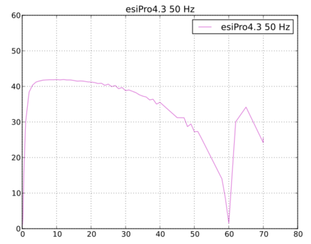
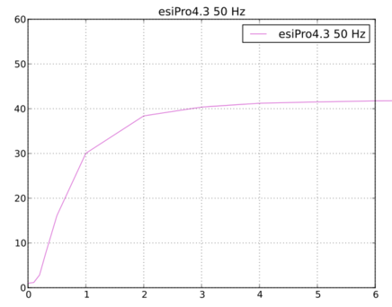
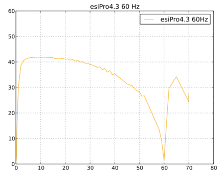
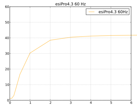

Other graphs and plots available from EEG Software as
requested.
|
Device
|
Serial number
|
Notes
|
|
Spectrum 2
|
12399
|
|
|
Spectrum 4
|
-------
|
Prototype without serial number
|
|
Brainmaster 2E
|
4290
|
|
|
Atlantis II
|
40403
|
|
|
esiPro 2.2
|
2C099132
|
|
|
esiPro 4.3
|
B117014
|
|
|
ProComp2
|
BC1063
|
|
|
ProComp+
|
AD3526
|
Flexpro=G3936
|
|
Infiniti
|
|
|
|
Pendant 9v
|
|
|
|
Pet2.0
|
|
|
|
QPET
|
|
|
|
BrainLynx
|
|
|
|
Optima
|
|
|
|
Neuroamp II
|
|
|
Appendix D:
Data formats
Common Definitions:
/*
common definitions */
/*
B4.0.0
030825.1126 hpl added definitions for
devices
030905.1545 hpl defined
c2mini
4.0.3g
040329.1650 hpl changed defs for
multitude of J&J devices
4.0.99
040622.1406 hpl game
defs
040830.1115 hpl reward mode group
def
041026.1520 hpl other rsf threads (like
tactile)
050422.1650 hpl added more device
codes
050427.1420 hpl added display band type
code
081104.1410 hpl Added
FR_BAND
091004.1708 mjb renamed FF_DAK1
FF_UNITY
100824.1345 hpl added definition for eye
status change
110209.1800 hpl pragma
pack
110228.1700 hpl revisions for
4ch
130513.1338 hpl added new multiple psync
modes
130729.1845 hpl added new psync
combinations
130731.0608 hpl added special R5 backing
store
140110.0800 hpl add place for lf
notch
140329.1020 hpl new action codes for cal
& impedance
150415.0840 hpl added uncouple
function
151222.1410 hpl added MULTIRAW
sizing
160606.0950 hpl change define to
maintain 16-chan compatability
*/
#ifndef
__eegerh__
#define
__eegerh__
//#define TIMELOOKER
1
#pragma
pack(push,1)
#define
STATE_REMAP 0 // indeterminate
#define
STATE_SETUP 1 // no drawing (not
running)
#define
STATE_SYNC 2 //
#define
STATE_QUIT 9 // end program
#define
STATE_DRAWABLE 10 // beginning of drawable
states
#define
STATE_INIT 10 // reinit state (starting a
'run')
#define
STATE_FREEZE 11
#define
STATE_PAUSE 12
#define
STATE_RUN 20
#define
STATE_REST 21
// these are the queue numbers for the
termination task queues
#define
HSD_MAIN 1
#define
HSD_THREAD 2
#define
RSF_MAIN 3
#define
RSF_THREAD 4
#define
GAME_THREAD 5
#define
RSF_OTHER 6
#define
DISP_SETUP 0
#define
DISP_HSD 1
#define
DISP_LONGT 2
#define
DISP_SPECT 3
#define
DISP_ZSCORE 4
#define
DISP_PERIODS 5
#define
DISP_FULLRAW 6 // future
#define
DISP_LAST DISP_PERIODS
#define
DISP_DEBUG 8
#define
DISP_HELP 9
#define
DISP_LSD 10 // there are up to 9
lsds
#define
DISP_LSD1 11
#define
DISP_EDITOR 19
#define
DISP_GAME 20
#define
SCRNMODE_SINGLE 2
#define
SCRNMODE_DUAL 1
#define
SCRNMODE_2COMP 0
#define
RAWD 1 // raw data
#define
PBACK 2 // playback
#define
SIGGEN 3 // signal
generator
#define
MAXUSEDSTREAMS 16 // most streams used for display (upper values
used internally)
#define
RAWUSEDSTREAMS 32
#define
MAXPERIPHS 4 // maximum number of peripheral
channels
#define
MAXPERIPHSALLOWED 3
#define
MAXLOWPASS 4 // maximum number of lowpass
channels/streams
#define
BACKDEPTH 6
#define
FLT_R1 MAXUSEDSTREAMS // offset to backing
store
#define
FLT_R2 (FLT_R1+MAXUSEDSTREAMS)
//offset to backing store for reward
1
#define
FLT_R3 (FLT_R2+MAXUSEDSTREAMS)
//offset to backing store for reward
2
#define
FLT_R4 (FLT_R3+MAXUSEDSTREAMS)
//offset to backing store for reward
3
#define
FLT_R5 (FLT_R4+MAXUSEDSTREAMS)
//offset to backing store for reward
4
// leave room for 5 more colums of data
for the psyncavg storage
#define
FLT_LIVE
(FLT_R5+MAXUSEDSTREAMS+(BACKDEPTH-1)*MAXUSEDSTREAMS)
// offset to live data for sham
runs
#define
FLT_NOTCH
(FLT_LIVE+MAXLOWPASS+MAXPERIPHS)
// offset to notch filter
coefficients
#define
FLT_ZNOTCH (FLT_NOTCH+MAXPERIPHS)
// offset for lf
notch
#define
FLT_NOLO (FLT_ZNOTCH+MAXPERIPHS)
// offset for non-lowpass,
non-dc-corrected raw values (for SCP and
VLF)
#define
FLT_PERIPH (FLT_NOLO+MAXLOWPASS)
// offset for peripheral state values
which may not be used...
#define
FLT_MULTIRAW (FLT_PERIPH+MAXPERIPHS)
// one buffer pointer for multichan
raw
#define
FLT_SIZER (FLT_MULTIRAW+1) // allocation counter for
states
#define
MAXPERIODS 128 // maximum number of periods in a
session
#define
MAXREWARDS 4 // maximum number of reward
streams
#define
MAXDEVICES 2 // maximum number of input
devices
#define
MAXDEVCHANNELS 4 // maximum number of highspeed channels per
device
#define
MAXSTRANDS 8 // strands in EGS
games
#define
MAXREWARDSTRANDS 4 // maximum number of reward
strands
// message
ids
#define
EEGMBASE 0x1000
#define
EMSG_RSFTIME WM_APP+EEGMBASE+ 0
// hs timer
message
#define
EMSG_RSFWDOG WM_APP+EEGMBASE+ 1
// sent to OC to show
alive
#define
EMSG_HSDTIME WM_APP+EEGMBASE+100
// time to
run
#define
EMSG_HSDWDOG WM_APP+EEGMBASE+101
// sent to OC to show
alive
#define
EMSG_OCWDOG WM_APP+EEGMBASE+201
// sent by OC to RSF to show
alive
#define
EMSG_OCACT WM_APP+EEGMBASE+202
// operator control message to
RSF
// the GROUP
codes
#define
GROUP_DC 0 // Display/control
settings
#define
GROUP_SCALE 1 //Scale settings
#define
GROUP_MODE 2 //Mode changes (up/down, model,
etc)
#define
GROUP_RWD 3 //reward mode
changes
#define
GROUP_SITE 4 //Site location
change
#define
GROUP_STAGE 5 // Stage setting
#define
GROUP_THRESH 6 //Thresh settings
#define
GROUP_LOFR 7 // low freq or center
freq
#define
GROUP_HIFR 8 // high freq or
width
#define
GROUP_AGOAL 9 // autoset (1 bit), % (7 bits), time (byte),
min (byte), max (byte)
#define
GROUP_MISC 14 // some kind of setting to record (like
integration time)
#define
GROUP_EVENT 15 // some kind of
event
// the ACTION
codes
#define
ACTION_SET 00 // just set the
value
#define
ACTION_KEY 01 // keycode
#define
ACTION_MISC 02 // misc meaning
#define
ACTION_RECORD 03
#define
ACTION_INPUTLOSS 11 // channel is 1 back and 0 for
loss
#define
ACTION_NORMAL 12 // device into normal
mode
#define
ACTION_IMPEDANCE 13
#define
ACTION_CALMODE 14
#define
ACTION_REWARD 15 // reward granted
#define
ACTION_FBACK 16 // begin feedback
#define
ACTION_PAUSE 17
#define
ACTION_USER 18 // user event
(f8)
#define
ACTION_USERM 19 // user event with
message
#define
ACTION_QUIT 20 // quit session
#define
MAKE_ACTIONCODE(group,action,stream) (((group & 0x0f) <<
12) | ((action & 0xff) << 4) | (stream &
0x0f))
#define
ACTIONCODE_GROUP(ac) ((ac >> 12) &
0x0f)
#define
ACTIONCODE_ACTION(ac) ((ac >> 4) &
0xff)
#define
ACTIONCODE_STREAM(ac) ( ac &
0x0f)
// the stage kind
codes
#define
ST_SETUP 0
#define
ST_RUN 1
#define
ST_PAUSE 2
#define
ST_EXIT 3
#define
ST_PERIPH 4
#define
ST_BASELINE 5
// the stage sequence
codes
#define
SEQ_INIT 0
#define
SEQ_PAUSE 1
#define
SEQ_RUN 2
#define
SEQ_REST 3
#define
SEQ_STAGEP 4
#define
SEQ_CHANGE 5
// message block
structure
typedef
struct
_mymsgblock_
{
short
code;
// why
there is a block
short
len;
//
number bytes INCLUDING block
headers
long
filler;
//
forcing to 16
union
{
double
d;
long
l[2];
short
s[4];
char
c[8];
}
u;
}
MYMSGBLOCK;
#define
MB_KEY 1 // means a
keycode in s[0];
#define
MB_ACTION 2 // means an
action code in s[0];
#define
MB_KEYBD 3 // WM_CHAR
keys for general typing
#define
MBMOD_SHIFT 1 // shift
key
#define
MBMOD_CTRL 2 // ctrl
key
#define
MBMOD_ALT 4 // alt
key
typedef
struct
_fcmd_
{
unsigned
char
funct;
//Function code
8
unsigned
char
flags;
//flag
bits 8
//
rrxxgemd
//
|---- 'Display' this stream
//
|----- multiple inputs
//
|------ more than up/down rewards
allowed
//
|------- outputs to game
//
|-------- QPSlag
//
|--------- QPSdev
//
||---------- backing set (0-3)selects
FLT_R1->FLT_R4
//
unsigned
char
grpstream;
//
ggssssss
//
||||||-----output stream
//
||-----------reward group
unsigned
char
procmode;
//
code for proc mode
char
numinp;
//
number of inputs 8
char
inch[3];
//
input array 24 up to 6 inputs packed as seq of bytes, each 4 bits
wide
char
numinhib;
//
number of inhibits 8
char
inhib[3];
//
array 24 up to 6 inhibits packed as seq of
bytes
}
FCMD;
#define
FCMD_FLAG_DISPLAY 1
#define
FCMD_FLAG_MULTINP 2
#define
FCMD_FLAG_EXTRA 4
#define
FCMD_FLAG_GAME 8
#define
FCMD_FLAG_QPSLAG 0x10
#define
FCMD_FLAG_QPSDEV 0x20
//
stream usage codes
//
These orders must match parblock.py
!!!!!!
#define
SUSE_RAW 1
#define
SUSE_INHIB 2
#define
SUSE_REWARD 3
#define
SUSE_MONITOR 4
#define
SUSE_DISPLAY 5
#define
MAX_FILTER_MODES 32 // in a
single session
#define
MAX_FM_FUNCTIONS 32 // most
filter functions per layout
//
filter function names
//
These names/orders must match parblock.py
!!!!!!
#define
FF_END 0 //END of
function list
#define
FF_LOWPASS 1 //lowpass
#define
FF_BANDPASS 2 //bandpass
#define
FF_DIFFER 3 //difference
#define
FF_SYNCH 4 //synch
reward
#define
FF_COMOD 5 //comod
reward
#define
FF_GLCOM 6 // global
comod
#define
FF_MINUS 7 //
XminusY
#define
FF_SMRREW 8 //single SMR
reward
#define
FF_ATREW 9 //single AT
reward
#define
FF_COHERE 10 // coherence
mode
#define
FF_MULTIREW 11 //
multi-reward
#define
FF_RATIO 12 //
ratio
#define
FF_DAKCOH 13
#define
FF_DAKPHASE 14
#define
FF_ZSCOREAA 15
#define
FF_ZSCORECO 16
#define
FF_ZSCOREPH 17
#define
FF_ZSCOREAPA 18
#define
FF_ZSCOREAPB 19
#define
FF_ZSCORERPA 20
#define
FF_ZSCORERPB 21
#define
FF_ZSCOREPRA 22
#define
FF_ZSCOREPRB 23
#define
FF_DC 24
#define
FF_UNITY 25
#define
FF_DAK2 26
#define
FF_DAK3 27
#define
FF_DAK4 28
#define
FF_DIFFSUM 29 // added for
Hirschberg study
#define
FF_ZCOMPOSITE 30
#define
FF_QAVGPSYNC 31 // 4-ch
averaged psyncs
#define
FF_ZQAVGCO 32 // zscore
4-ch averaged coherence
#define
FF_QPSFUN 33 // new psync
modes
#define
FF_UNCOUPLE 34
#define
FF_QASFUN 35
//
definitions used in .bfn files for filter
operations
// may
be or'ed together
#define
FB_SYNC 1 // coherence
(synchrony)
#define
FB_ZSCORE 2 // ANI
zscore
#define
FB_4CHAN 4
#define
FB_QOPS 8 //QPS and
QAS
#define
FB_ADV 16 // advanced
FB items
#define
FR_UP 0 // normal
"UP" reward
#define
FR_DOWN 1 // down
reward
#define
FR_CENTER 2
#define
FR_ELEVATE 3
#define
FR_DEVUP 4
#define
FR_DEVDOWN 5
#define
FR_BAND 6
#define
FR_ZCOMP 7
#define
GMISC_INTEGTIME 1 // filter
integration time
#define
GMISC_TIMEONSTATE 2
#define
GMISC_PERCENTONSTATE 3
#define
GMISC_MINREWARD_TIME 4
#define
GMISC_EYESTATUS 5
#define
GMISC_ZCPARAMETER 16
#define
GMISC_ZCCHAN 17
#define
GMISC_ZCBAND 18
#define
GMISC_ZCTHRSH 19
#define
GMISC_ZCPERCENT 20
#define
GMISC_ZCENABLE 21
#define
GMISC_ZCDISABLE 22
#pragma
pack(pop)
#endif
Raw
Data File Format
/* file
format header */
/*
RAW data
files
The raw filename is constructed from the
client code (<32 characters, no embedded
spaces
or special characters) and a numerical
code. As with the summary filename, a 6
digit
code will be APPENDED to the client
code. The 6 digits are the 4-digit partial
Julian
daycode and a uniqueness-guaranteeing
sequence code.
The filename structure will be
CCjjjjqq.RAW where CC is the 1- to 31-character
client
id code, jjjj is the part of the Julian
date, and qq is the sequence number.
Raw File
Format
This note describes the internal format
of a raw data file saved by eegsoft.
It is the intention of this description
to provide both the baseline format
and various
extensions.
Basically, a 'raw' file contains 'raw'
data acquired during a session along
with operator actions time-correlated
with the data. Up to 16 channels of
data are provided for, each with
scaling, format definitions, etc.
Channel data is stored end-to-end, not
interleaved. There may be multiple
blocks of channel data for each channel
in the file. Multiple blocks will be
time-sequential in the file although the
block positions imply no time
relationships between channels. By this,
I mean that a low speed block may
contain timed samples over a longer time
period than higher-rate blocks
before and after it sequentially in the
file. The actual I/O may/will be
double-buffered to handle the 'long'
time it takes to write data blocks to
a file.
Header
format
Content Symbol Type Length
Notes
File type code char 4
RAWD
Format code short int 2 bytes Format
code is major.minor ,
major* 100
format 0.1 == 1, 1.3 ==
103
Datecode long int 4 Abs
date
Timecode long int 4 Seconds since
midnight of FB start time
Client code char 32 client id
code
Client name char 64 client
name
Machine ID long int 4 dongle code for
now
Sample Clock Rate short int 2 e.g. 160,
256, 512
number of channels short int 2 1 to
16
format string char
16
offset of
controls
block long int 4 byte
offset
Max datablock size long int 4 size of
largest data block
must allocate (1+ #chans)*2 of
these
Chan0Block 16 channel
block
Chan1Block
Chan2Block
Chan3Block
Chan4Block
Chan5Block
Chan6Block
Chan7Block
Chan8Block
Chan9Block
Chan10Block
Chan11Block
Chan12Block
Chan13Block
Chan14Block
Chan15Block
Format of each channel
block
Content Symbol Type Length
Notes
Type code unsigned 2 drives format of
data
subrate unsigned 2 currently only 1 or 8
for procomps
SequenceCode long 4 unique sequence code
for stream
ID long 4 procomp serial number or
??
Scale factor double 8 lsb scale factor
of data
offset of 1st data block long 4 byte
offset
Format of a data
block
Content Symbol Type Length
Notes
Length of block long int 4 length in
bytes of block incl header
Type code 2
0=uncompressed
time stamp of 1st data long int 4
real-time cycle count
offset of next block long int 4 byte
offset of next block
data 2
---- 2
Format of controls
block
Content Symbol Type Length
Notes
Length of block long int 4 length in
bytes of block incl header
offset of next control blk long 4 byte
offset
sub-blocks.
Format of control sub-blocks (each
corresponding to one action!)
length 2 bytes sub-block length
including this header
action code 2 bytes LOTS of
codes
Code definitions use lots of major
grouping codes for easier
categorization.
Lower 4 bits of every code reflects
(possible) channel.
time stamp 4 bytes real-time cycle
count
data double
char [8]
long[2] 8
bytes
this may be the beginning of a variable
length text field also
(for event reasons and
such)
Action
coding:
Multiple actions with same time stamp
imply a major action (such as
beginning
a session using the previous
settings!!).
MMMMAAAAAAAACCCC
MMMM is the major
grouping
00 Display/control
settings
01 Scale
02 Mode changes (up/down, model,
etc)
03
04 Site location
change
05 User
event
06 Threshold
setting
07 Low freq
setting
08 high freq
setting
AAAAAAAA is the action
code
tbd - defined in
eeger.h
CCCC is the channel for channel-related
action codes
060214.1135 hpl reverted to 104 version
temporarily
070822.1040 hpl made some shorts into
unsigned short
100621.1617 hpl added subset code to
header and biological sex
110228.1500 hpl 110 revised header
layout and made room for more peripheral
data
140221.0930 hpl added some optional data
storage for high speed amplitude data for NF
study
*/
#ifndef
__rawformath__
#define
__rawformath__
#pragma
pack(push,1)
#define
RAWVERSION 110 // odd versions are the 'compressed'
version
// of the next lower even file
format
// this makes it easy to
discriminate/convert
#define
MAX_CHUNKS 64 // maximum number of data chunks in a
file
#define
MAX_ACTION_SIZE 4096 // max size of an action
chunk
// there are 16 of these in the header
block
typedef
struct
_RAWCHD_
{
#if
RAWVERSION >= 110
unsigned
char
typecode;
//my
code for device type for eeg data (DEV_
codes
unsigned
char
channel;
//
channel number for data A=0, B=1, C=2, D=3, whatever for
peripherals, etc.
#else
unsigned
short
typecode;
//which device produced
data
#endif
unsigned
char
subrate;
//currently only 1 or 8 for
procomps
//
Note: subrate == 1 means raw EEG
data
//
subrate != 1 ==> peripheral
data
unsigned
char
datatype;
//
kind of data
// 0
== EEG, 1= undifferentiated peripheral data, 2->255
???
long
ID;
//procomp serial number or peripheral
channel
double
scalefactor;
//lsb
scale factor of data
//
peripheral data has a scalefactor of
???
long
dboffset;
//byte
offset to first data block
}
RAWCHD;
//
this is the actual file header
typedef
struct
_RAWHD_
{
char
filetype[4];
//RAWD
short
formatcode;
//Format code is major.minor ,major*
100
//format 0.1 == 1, 1.3 ==
103
long
datecode;
//Abs
date
long
timecode;
//Seconds since midnight of FB start
time
char
clientcode[32];
//client id
code
char
clientname[64];
//client
name
long
machineID;
//dongle code for
now
short
clockrate;
//e.g.
160, 256, 512
short
numberofchannels;
//1 to
16
char
formatstring[16];
//
contains format string at recording
time
long
SequenceCode[MAX_FILTER_MODES];
//
sequence codes for session !!!
long
cboffset;
//byte
offset of controls block
long
maxdatablocksize;
//size
of largest data block
//must
allocate (1+ #chans)*2 of these
#if
RAWVERSION < 110
RAWCHD
chd[15];
//channel head
blocks
char
lcode;
// 0
for unk, 1 for therap, 2 for
remote
char
subset;
//
which subset of current structure this
is
char
bsex;
//
either 0 (unk), 'M','F'
char
filler[17];
//
make up for stealing one chd
#if
RAWVERSION >= 106
long
birthdate;
//
birthdate in "proleptic Gregorian" == "absolute date" format 1=
01/01/0001
#endif
#if
RAWVERSION >= 108
char
xguid[32];
//
'original' writer of file
#endif
#else
char
lcode;
// 0
for unk, 1 for therap, 2 for remote, 3 for
sham
char
subset;
//
which subset of current structure this
is
char
bsex;
//
either 0 (unk), 'M','F'
char
filler[17];
long
birthdate;
//
birthdate in "proleptic Gregorian" == "absolute date" format 1=
01/01/0001
char
xguid[32];
//
'original' writer of file
long
chdoffset;
//
byte offset to first (of the sequential) channel block
items
long
summaryoffset;
//
byte offset to included summary file if there is one
appended!!!!
RAWCHD
chd[16];
//channel head
blocks
long
amplvalues;
//byte
offset of amplitude data iff subset >= 2. Zero means nothing
stored
long
future;
#endif
}
RAWHEAD;
typedef
struct
_OLDRAWHD_
{
char
filetype[4];
//RAWD
short
formatcode;
//Format code is major.minor ,major*
100
//format 0.1 == 1, 1.3 ==
103
long
datecode;
//Abs
date
long
timecode;
//Seconds since midnight of FB start
time
char
clientcode[32];
//client id
code
char
clientname[64];
//client
name
long
machineID;
//dongle code for
now
short
clockrate;
//e.g.
160, 256, 512
short
numberofchannels;
//1 to
16
char
formatstring[16];
//
contains format string at recording
time
long
SequenceCode[MAX_FILTER_MODES];
//
sequence codes for session !!!
long
cboffset;
//byte
offset of controls block
long
maxdatablocksize;
//size
of largest data block
//must
allocate (1+ #chans)*2 of these
RAWCHD
chd[15];
//channel head
blocks
char
lcode;
// 0
for unk, 1 for therap, 2 for
remote
char
subset;
//
which subset of current structure this
is
char
bsex;
//
either 0 (unk), 'M','F'
char
filler[17];
//
make up for stealing one chd
#if
RAWVERSION >= 106
long
birthdate;
//
birthdate in "proleptic Gregorian" == "absolute date" format 1=
01/01/0001
#endif
#if
RAWVERSION >= 108
char
xguid[32];
//
'original' writer of file
#endif
}
OLDRAWHEAD;
//
there is one of these at the head of each chunk of raw
data
typedef
struct
_RAWDB_
{
long
length;
//length in bytes of block incl
header
unsigned
char
typecode;
//device it came
from
unsigned
char
datacode;
// how
to decode special data
long
timestamp;
//real-time cycle count of first
sample
long
nextoffset;
//byte
offset of next block
//short data[1]; // data
sample
// ...
more samples
}
RAWDB;
//
there is one of these for each 'action'
subblock
typedef
struct
_RAWSUB_
{
unsigned
short
length;
//sub-block length including this
header
unsigned
short
actioncode;
//LOTS
of codes
long
timestamp;
//real-time cycle count of this
action
union
{
double
data1;
//this
may be the beginning of a variable length text field also (for
event reasons and such)
char
text[8];
long
ld[2];
float
fdata[2];
short
twobytes[4];
}
d;
}
RAWSUB;
//
there is one of these for each chunk of
actions
typedef
struct
_RAWCB_
{
long
length;
//length in bytes of block incl
header
long
nextoffset;
//
offset in bytes of next control
blk
//RAWSUB blocks[1]; //
sub-blocks.
}
RAWCB;
/*
ampl
values are recorded at 'clockrate' in a normalized format (fixed
point scaled 100) in a signed
short
range
is thus 0 - 327.67 microvolts
The
ampl values are the short-term moving averages used for threshold
decisions, etc.
Each
sequential time sample value contains 'numberofchannels' data
samples so careful about sizing if there
are
peripheral channels specified. Data is only
recorded if the option was specified at run
time.
All
data is stored in memory until end of
session.
*/
#pragma
pack(pop)
#endif
Summary File Format
/*
Summary files consist of a header and a series
of data blocks containing the once per
second
average values, the threshold settings, and a
composite reward flag bit for each
filtered
channel. Additional information is saved (at
the slow 1 Hz rate) for later
analysis/understanding
Part of
the summary data filename is constructed from the 4 lower digits of
the Julian date.
Julian dates in the range 1995-2023 are all
greater than 245000 and less than
255000.
Additionally, (to handle multiple and aborted
sessions in the same day),
a 2-digit sequence number will be used to
ensure that there are no filename
conflicts.
The filename structure will be Sjjjjqq.SUM
where jjjjj is the aforementioned part of
the
Julian date and qq is the sequence number.
Internally, the actual client identifiers
are
stored in the
file.
Summary
file data format
This
file consists of a header and a series of data blocks containing
the
once per second average values, the threshold
settings, and a composite
reward flag bit for each filtered
channel.
Additional information is saved (at the slow 1
Hz rate) for later
analysis/understanding.
Header
format:
Content Symbol Type Length
Notes
File type code char 4
SUMD
Format code short int 2 bytes Format code is
major.minor
major*
100
format 0.1 == 1, 1.3 ==
103
Protocol code char 4 Like SMR AT EXP with
trailing null bytes
number of traces/chan byte 1 1 to 16 filtered
traces, 1-16 channels
number of lowpass ch byte
1
Datecode long int Abs
date
Timecode long int Seconds since midnight local
time
Client code char 32 client id
code
Client name char 64 client
name
game name char
32
Block
format:
Content
Symbol Type Length Notes
length unsigned 2 length of this block in
bytes
format code unsigned 1
code
time stamp of 1st data unsigned 2 in seconds
relative to base timecode
data
follows
Format
codes:
1 data
2
threshold
3
frequency
4
channel/site
5 Summary
6
Scale
7 Period
For
data blocks
Content Symbol Type Length
Notes
0th average value short int 2 microvolts *
100; negative means reward for at least one sample in 1 second
interval
Note that maximum average microvolt
value
.. is 327.67 microvolts (times
100!!)
nth average value n is number of traces
-1
0th average value for the next
second!!!
-----------
For
threshold blocks
Content Symbol Type Length
Notes
0th threshold unsigned 2 microvolts *
100
..
nth
threshold n is number of traces
-1
For
frequency blocks
Content Symbol Type Length
Notes
0th low freq unsigned 2 low freq in 1000ths of
Hz; 4250 = 4.25 Hz
0th high freq unsigned 2 in 1000ths of
Hz
-------
nth low
freq n is number traces - 1
nth high freq
For
site/channel blocks
Content Symbol Type Length
Notes
Mode code char 4 kind of feedback
mode
Chan code int 1 channel for
input
Site code char 11 char string of
sites
Chan code pairs of entries for all USED
channels
Site code
---------
Current
schemes will only have ONE or TWO channels of input although
the
format allows
more.
Summary
block
Content Symbol Type Length
Notes
0th average value coded 2 microvolts *
100
Note that maximum average microvolt
value
.. is 327.67 microvolts (times
100!!)
0th percentage in % times
100
-----------
nth percentage
nth average value n is number of traces
-1
Scale
block
Content Symbol Type Length
Notes
0th scale unsigned 2 microvolts *
100
..
nth
scale n is number of traces -1
030326.1151 hpl added mark data but kept
version 106
040127.1152 hpl changed to unsigned short
length and version 108
4.1.xx
040913.1130 hpl version 110 - added overall
reward percent to period data
050420.1115 hpl version 112 - scab on total
reward % to percentage values (fake extra trace
data)
060120.1400 hpl version 114 - add SUM_PERIPH
to data, go to long header
lengths
060214.1135 hpl reverted to 112 structures
temporarily
070129.1437 hpl 116 adds zscore
data
110209.1800 hpl pragma
pack
110228.1510 hpl 118 revised structure to
remove xdata and handle both 2- and 4-channel
zscore
140327.1725 hpl intg negative NOT during
period means its impedance value/100 clamped to
max
160606.0950 hpl change define to maintain
16-chan compatability
170912.1105 hpl added qps data definition for
research
*/
#ifndef
__SUMFORMATH__
#define
__SUMFORMATH__
#include
"eeger.h"
#pragma
pack(push,1)
#define
SUMVERSION 118
// file
header
typedef
struct
_SUMHD_
{
char
filetype[4];
//
SUMD
short
formatcode;
//Format code is major.minor ,major*
100
//format 0.1
== 1, 1.3 == 103
char
protocolcode[4];
//Like
SMR AT EXP with trailing null
bytes
char
numberoftraces;
//1 to
16 filtered traces, 1-16
channels
char
numberlowpass;
//
number lowpass channels
long
datecode;
//Abs
date
long
timecode;
//Seconds since midnight local
time
long
SequenceCode[MAX_FILTER_MODES];//
what kind of sequence codes were
possible
char
formatstring[MAXUSEDSTREAMS];
//
contains format string at recording
time
char
gameid[30];
char
lcode;
// 1
for therapist, 2 for
remote
char
spare;
char
clientcode[32];
char
clientname[64];
// following
new in 118
char
numberperiph;
//number of peripheral
channels
float
multiplier[MAXUSEDSTREAMS+MAXPERIPHS];
//
scaling factor for data - mostly
peripherals!!
}
SUMHD;
typedef
struct
_SUMBLKHD_
{
#if SUMVERSION >=
114
unsigned
long
length;
//length of this block in
bytes
#else
unsigned
short
length;
#endif
short
formatcode;
//
SUM_ codes
unsigned
short
timestamp;
//
seconds relative to base timecode of 1st
data
}
SUMBLKHD;
typedef
struct
_SUMFR_
{
SUMBLKHD
blkhd;
struct
{
unsigned
short
low;
// low
freq in 1000ths of Hz; 4250 = 4.25
Hz
unsigned
short
high;
// in
1000ths of Hz
}
freq[1];
// nth low
freq n is number traces -
1
// nth high
freq
}
SUMFREQ;
typedef
struct
_SUMCD_
{
SUMBLKHD
blkhd;
char
modename[16];
//kind
of feedback mode
struct
{
char
channel;
//channel for
input
char
sites[11];
//string of
sites
}
site[1];
//Chan code
pairs of entries for all USED
channels
//Site
code
}
SUMCD;
//missing
data points denoted by value of
0xffff
typedef
struct
_SUMDTA_
{
SUMBLKHD
blkhd;
union
{
short
value;
//microvolts * 100; negative means reward for
at least one sample in 1 second
interval
// Note that
maximum average microvolt
value
// is 327.67
microvolts (times 100!!)
unsigned
short
threshold;//microvolts *
100
unsigned
short
average;
//microvolts * 100 (long term
average)
//Note that
maximum average microvolt value is 327.67 microvolts (times
100!!)
unsigned
short
percentage;
// %
times 100
// I add an
EXTRA value == total reward percentage
on
unsigned
short
scale;
//
microvolts * 100
unsigned
short
periph;
//
something * 10
}
trace[1];
// nth
percentage
//nth
average value n is number of traces
-1
}
SUMDATA;
typedef
struct
_SUMPER_
{
SUMBLKHD
blkhd;
unsigned
short
period;
//
period number
unsigned
short
seconds;
//
delta seconds in period
unsigned
short
score;
//
delta score for period
unsigned
short
overall_reward;
//
overall reward % new in
110
char
gamename[64];
//
rightmost 64 chars of game
'name'/path
// begin
junk
// unused
since at least 4.2.0
struct
{
unsigned
short
beginampl;
// 1st
second ampl * 100
unsigned
short
aveampl;
//
average amplitude * 100
unsigned
short
endampl;
// end
of period ampl * 100
unsigned
short
lowfreq;
//
band low freq * 1000
unsigned
short
highfreq;
//
band high freq * 1000
}
xbands[4];
// end
junk
struct
{
unsigned
short
average;
//
ending long-term average *
100
unsigned
short
percent;
//
ending percent over threshold
*100
unsigned
short
threshold;
//
ending threshold value *
100
unsigned
short
lowfreq;
//
ending low freq limit *
1000
unsigned
short
highfreq;
//
ending high freq limit *
1000
char
sitelist[12];
//
ending site list
}
streamval[1];
// one
for each stream
}
SUMPERIOD;
typedef
struct
_SUMMODE_
{
SUMBLKHD
blkhd;
long
seqcode;
//
sequence code now switching
to
char
modename[16];
//kind
of feedback mode
unsigned
char
rewardcode[16];
//
codes for reward
directions
}
SUMMODE;
typedef
struct
_SUMMARK_
{
SUMBLKHD
blkhd;
unsigned
short
msglength;
//
number of bytes in msg
char
msg[1];
//
where mesg starts
}
SUMMARK;
typedef
struct
_SUMZSCORE_
{
SUMBLKHD
blkhd;
short
int
kindcode;
// 0
means all 2ch terms are included;1 means only products, 2= all
4ch,3 = only 4ch
products
union
__kinddata__
{
struct
__chans4__
{
struct
{
short
int
zaa[6][10];
//
microvolts*100
short
int
zco[6][10];
short
int
zap[6][10];
}
products[1];
struct
{
short
int
zap[4][10];
// 1st
8 are chan A
short
int
zrp[4][10];
short
int
zpr[4][10];
// 1st
10 are chan A
}
terms[1];
}
chans4;
struct
__chans2__
{
struct
{
short
int
zaa[1][10];
//
microvolts*100
short
int
zco[1][10];
short
int
zap[1][10];
}
products[1];
struct
{
short
int
zap[2][10];
// 1st
8 are chan A
short
int
zrp[2][10];
short
int
zpr[2][10];
// 1st
10 are chan A
}
terms[1];
}
chans2;
}
kinddata;
}
SUMZSCORE;
typedef
struct
_SUMQPS_
{
SUMBLKHD
blkhd;
struct
_dta_
{
short
int
qpsover;
short
int
qpsvg;
short
int
qpsdev;
}
dta[4];
short
int
qpspercent;
short
int
qpsvalue;
}
SUMQPS;
//WARNING:
storage.cpp and sumfile.py (and
others!!??)
// make
assumptions about these
numbers!!!!!
#define SUM_DATA
0 //SUMDATA
#define SUM_THRESH
1 //SUMDATA
#define SUM_AVERAGE
2 //SUMDATA
#define SUM_PERCENT
3 //SUMDATA
#define SUM_FREQ
4 //SUMFREQ
#define SUM_SCALE
5 //SUMSCALE
#define SUM_SITE
6 //SUMCD
#define SUM_PERIOD
7 //SUMPER
#define SUM_MODE
8
#define SUM_MARK
9
#define SUM_PERIPH
10 //SUMDATA
#define SUM_ZSCORE
11
#define SUM_QPS
12
#define SUM_LAST
12 // just the
highest number
#pragma
pack(pop)
#endif
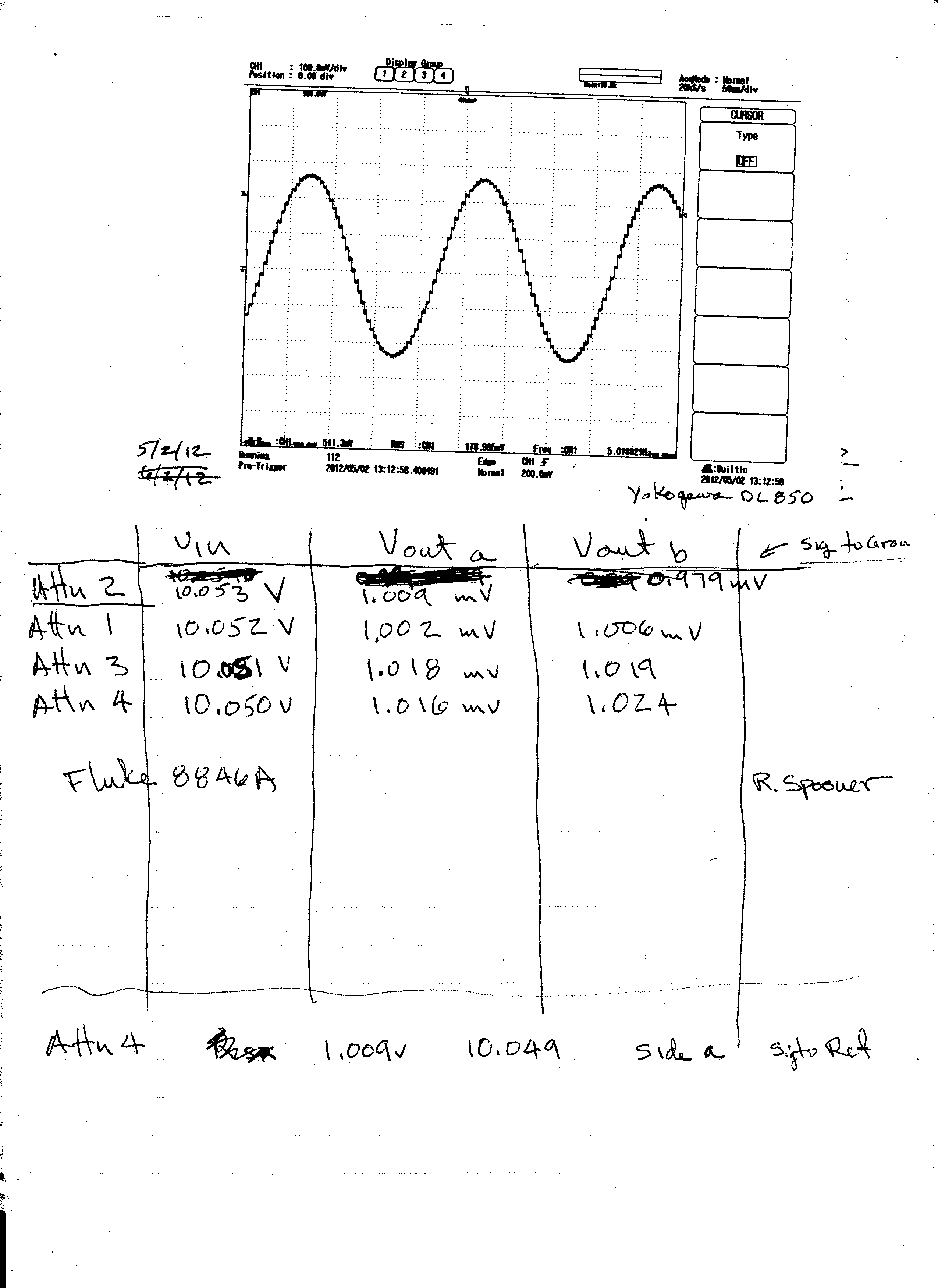
Appendix E: Data Acquisition Methodology
This document contains data acquired using normal versions of
EEGer4. The data is generated using a combination of a software and
hardware external to EEGer4 itself as described in Appendix F.
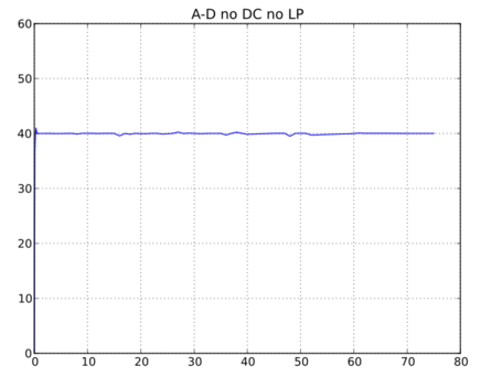
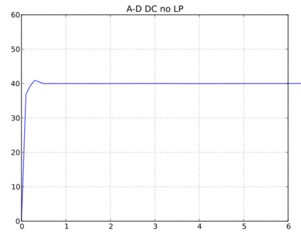
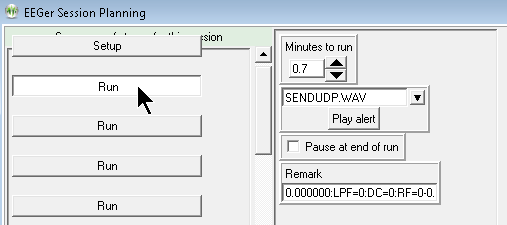
EEGer4 supports a special development mode where a specific run
stage comment in a session plan sends a UDP message to the signal
generator described in Appendix F. The message controls some EEGer
parameters and the frequency that the signal generator is to
supply. Critical parameters other than the frequency are the
settings for the lowpass filter and DC correction filters which can
be turned on/off depending on the test to be run. The EEGer4 setup
is done in session planning where the alert name must be
SENDUDP.WAV and the remark field contains the parameters.
Frequencies used in the test session plan are
0.0,0.1,0.2,0.3,0.5, Hz
1 to 40 Hz in 1 Hz steps
45.0,47.0,48.0,49.0,50.0,51.0,52.0,58.0,59.0,60.0,61.0,62.0,65.0,70.0
Hz
The run time chosen is long enough for the value smoothing to
occur so that values at the end of each period represent the
average value. Since there is no pause flag checked, run stages
continue to run until the end of the session. In this fashion, a
test run is semi-automated. Once started, the identical test
sequence is performed. Data for each run is available as summary
data outputs from the EEGer4 review process.
This method was used to generate the filter characteristics used
for the filter plots and the bandpass characteristics shown for
each amplifier/encoder.
Appendix F: Signal
Generator
Signal Generator
Technical Description
Version 1.12
Description
The signal generator tool provides a representative EEG signal
for tests of signal acquisition devices and for end-to-end testing
of the entire neurofeedback system.
Digital to Analog Converter
(DAC)
The DAC used for the signal generator tool is a USB-3101FS
16-bit four channel DAC manufactured by Measurement Computing
Corporation. It is supported by the MCC-provided InstaCAL
input/output interface library (which must be installed). The
device is a USB-2.0 controlled and powered device.
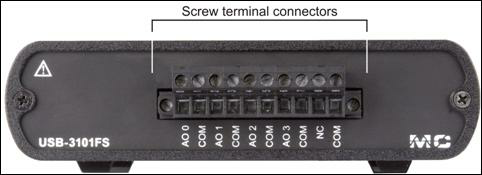
Figure 2:
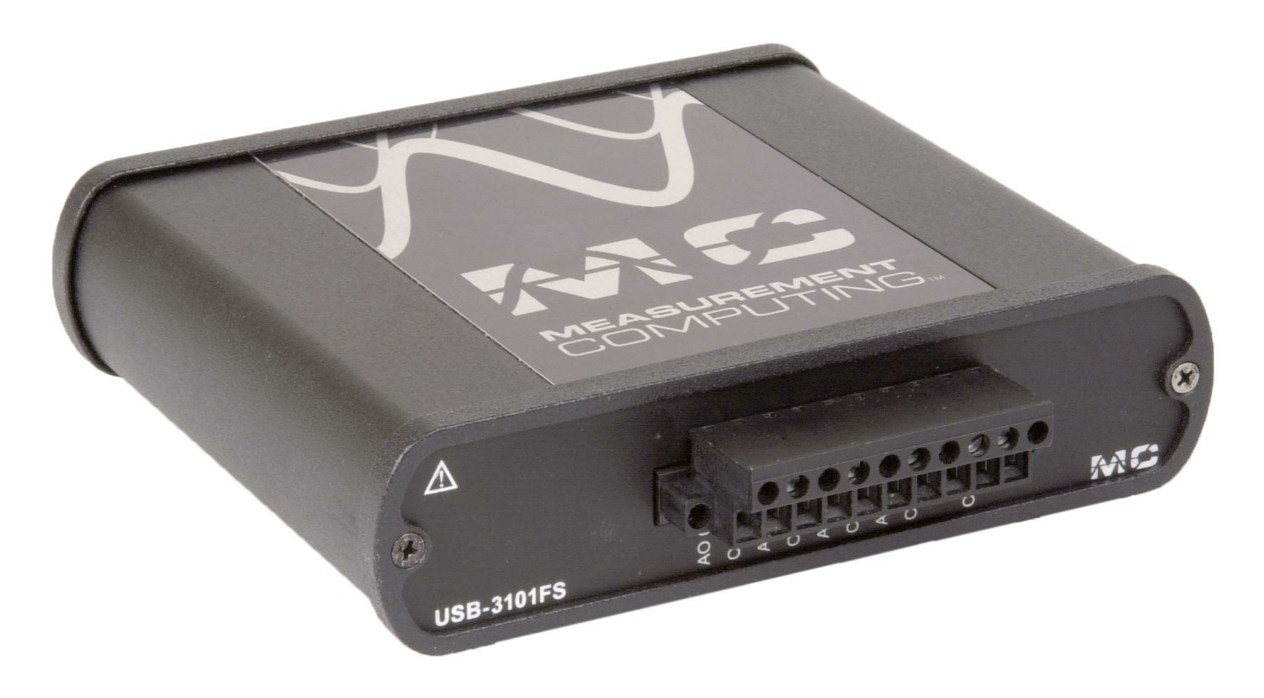
Figure 1:
Screw terminal
pin assignments
Terminal
Signal
0 AO 0
1 Common (COM)
2 AO 1
3 Common (COM)
4 AO 2
5 Common (COM)
6 AO 3
7 Common (COM)
8 NC (No
connection)
9 Common (COM)
Attenuator
The attenuator device is an internally manufactured purely
resistive voltage divider used to reduce the DAC outputs (0.5 volt)
to ranges appropriate for an EEG-level (50 microvolt) sensing
device.
Attenuator box.
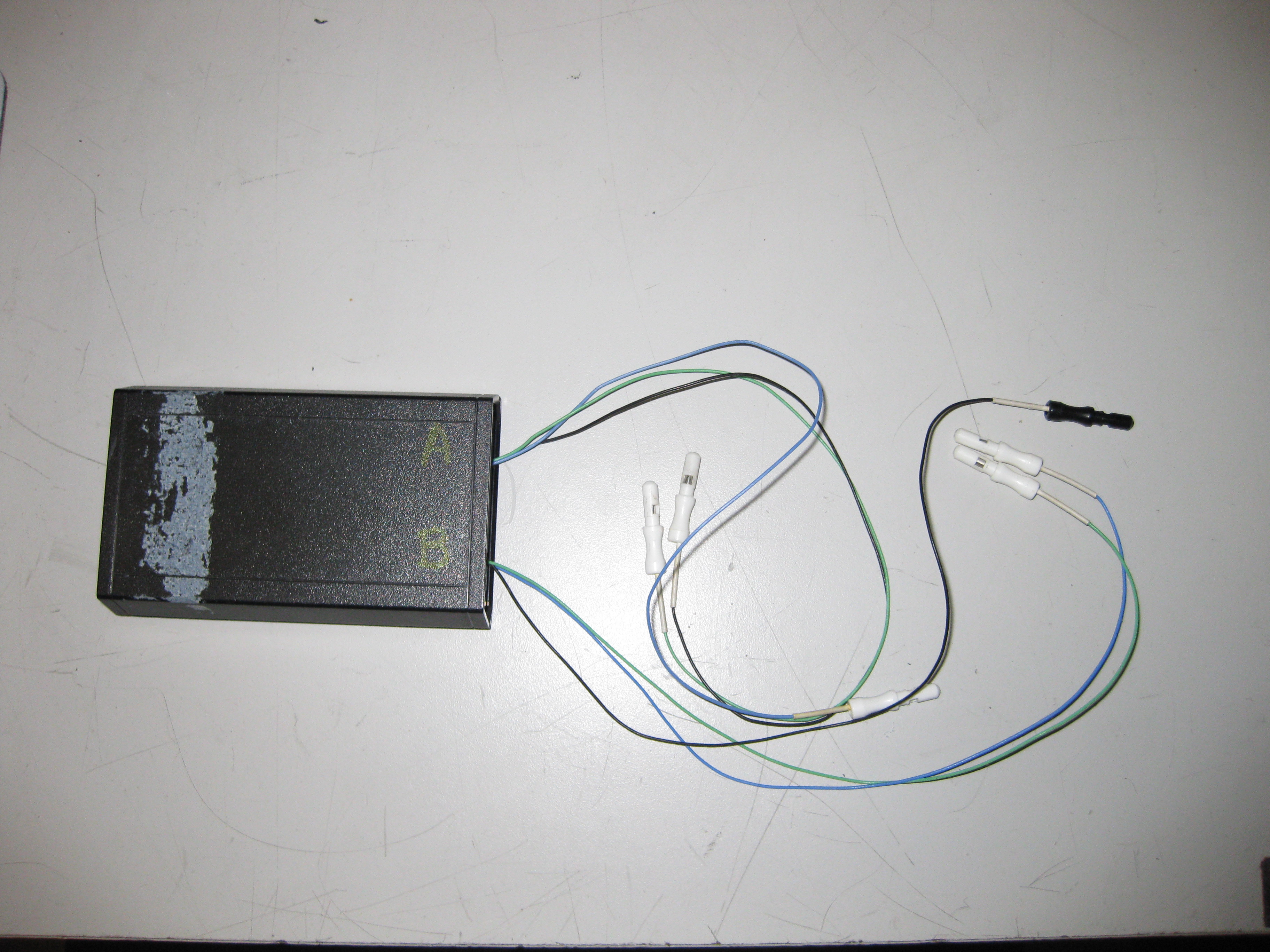
Internals of typical attenuator box.

Schematic of attenuator
box.
Cabling from USB-3101FS to
attenuator box.

Wiring diagram for cable
between USB-3101FS and attenuator box.

SigDriver
This software module contains the logic necessary to decode an
input data file (in EEGer .RAW format) and send it to the DAC. It
also provides the ability to generate simple sine wave signals and
to provide a spike impulse for testing of EEGer software. The user
interface for the module is implemented using FLTK, a user
interface library. Source code for this tool is maintained in the
revision control system. The module contains the following logical
functions:
mymain – builds the screen interface and calls the output
routine
runsome - the actual output routine
findfiles – determine which files are available
read_raw_file – reads/decodes a raw file
read_first_event – reads/decodes first text event in a raw file
(for titles)
synth_raw_file – creates equivalent of raw data in cases of
simple sine waves (manual) mode
sample – the actual computation of the output voltage for a
sample
CheckListener – support routine for automatic bandpass testing
which monitors for
frequency changes commanded by EEGer in test mode.
Because this program runs under Microsoft Windows, the
computation of the correct signal value takes into account the
erratic timing under Microsoft Windows and handles it
appropriately.
The format of the data listened for is a UDP message received
containing one block of data in this format:
|
0xe1
|
0
|
Size low
|
Size high
|
|
|
|
|
|
|
Text
|
Where “text” is an ASCII string in the following format:
freq:optn:optn:optn..
where only the first value (frequency value terminated by a
colon) is used by SigDriver. This value is forced into the manual
frequency setting for Sig1. At that time, all other values are set
to zero except the amplitude for Sig1 (set to 40) and the mask for
Sig1 (set to 3). Manual mode is forced on at that time.
The main screen is this:
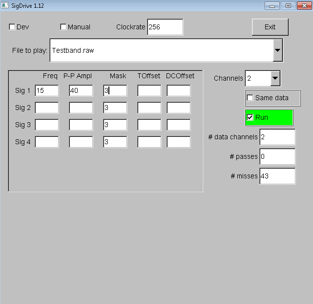
This reports that the testband file is being used as the signal
source, there are two channels of data in the source, we are NOT
forcing all the data channels to use one channel of data, and that
the signal driver is running.
The dropdown box at the top (File to play) gives the following
options (unless additional files are created using the FreqFileGen
tool described later):
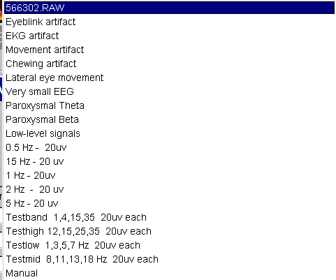
Selection of the Manual checkbox gives this screen:

where the yellow-highlighted region contains the values to
generate. Shown here in this example is a 10 Hz signal on channel 0
(A) and a 12 Hz signal on channel 1 (or B).
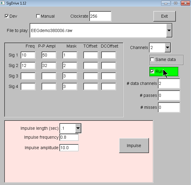
If the Dev checkbox is selected, the following screen shows the
additional options for the impulse generator:
Frequency File Generator
(FreqFileGen)
This module is a Python script which allows creation of complex
source signal files (in EEGer format suitable for replay in EEGer).
The screen looks like this:
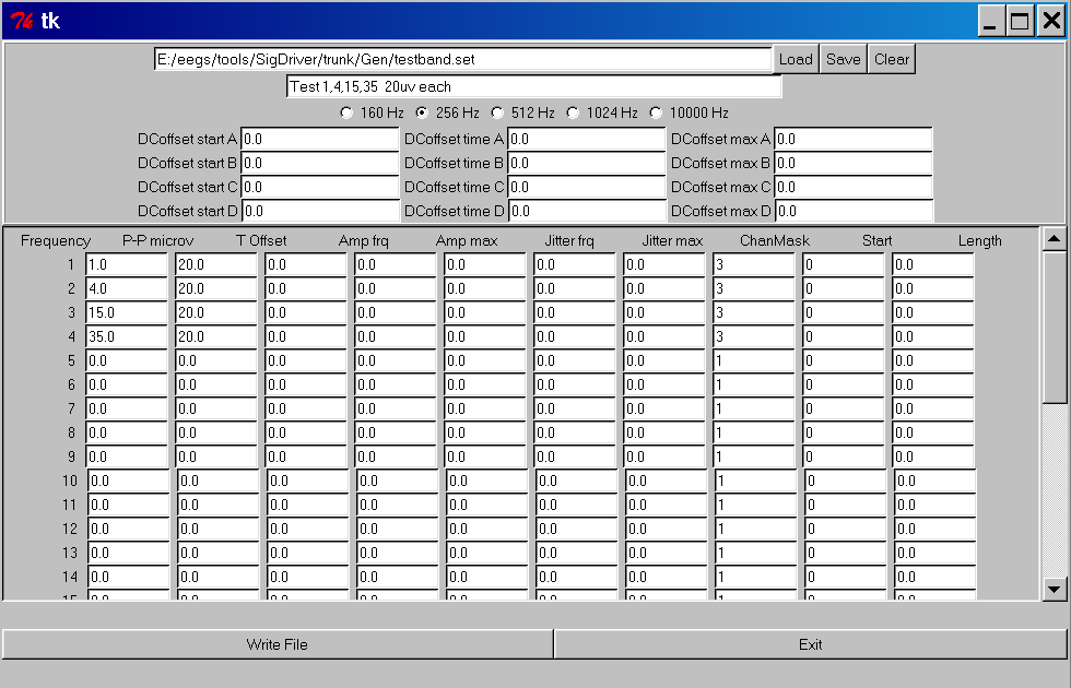
There are 32 source points, each of which can have the following
characteristics:
frequency
peak-peak voltage in microvolts
starting time offset of signal (in seconds)
amplitude variation frequency (rate of variation of
amplitude)
maximum amplitude of amplitude variation (amount of amplitude
variation)
jitter frequency (rate of variation of starting time)
jitter max (maximum amount of time variation)
Channel mask (bit mask for the output channels for the
signal)
Start (starting time of the signal)
length( length of time signal is generated – 0 means
forever)
In addition, each of the four possible channels can have a DC
offset, a DC offset variation, and a starting time for the DC
offset variation to test DC characteristics of AC and DC coupled
acquisition devices.
Calibration process
The signal generator tool must be periodically calibrated. The
calibration tool used is a Fluke 87-5 digital multimeter (DMM) or
equivalent which has a valid NIST-traceable calibration
certificate.
1. DISCONNECT signal block from USB-3101FS
Frequency/amplitude of signal generator:
2. The DMM is connected to the terminal block of the USB-3101FS
pins 0 (signal) and 1 (ground).
3. The SigDriver is started and Manual mode is selected.
4. The following parameters are sequentially entered in the
manual fields and results verified:
|
Frequency
|
Amplitude
|
Freq reading
|
Amplitude reading (true RMS)
|
|
2
|
10
|
2+- 0.3
|
0.10 +-.0 1
|
|
5
|
15
|
5 +-.3
|
0.15+-.01
|
|
10
|
20
|
10+- .3
|
0.20+-.01
|
|
12
|
25
|
12 +- .3
|
0.25+-.01
|
|
25
|
30
|
25+- .5
|
0.30+- .01
|
|
30
|
40
|
30 +- .5
|
0.40+-.01
|
|
50
|
60
|
50 +- .5
|
0.60+-.01
|
5. Repeats steps 2,3, and 4 for DMM connected to pins 2,4,6
making sure that the signal is routed to the correct channels
(mask=15)
This verifies the generation of signals has requisite
accuracy.
Attenuator box:
5. Using DMM, measure resistance between signal block pin 0 and
signal block pin 1 while attenuator box is connected to cable but
NOT to an acquisition device.
6. Verify resistance is 1,000,000 +- 20,000 ohms.
7. Measure resistance between signal and reference leads for
channel A on the attenuator box.
8. Verify resistance is 100 +- 3 ohms
9. Repeat steps 5-6 for pins 2 and 1 on the signal block.
10. Repeat stems 7 and 8 for leads for channel B on the
attenuator box.
Each attenuator box needs to be calibrated and a calibration
sticker attached.
11. Fill in the calibration test log and sign where
appropriate.
This procedure needs to be once per year or sooner if repairs
are needed on any component or the driver software is changed.
Initial calibration data