EEGer4™
Neurofeedback
Software
Operator's Manual
Version 4.4.0
Technical Support: EEG Store (800) 789-3456
Customer Support: EEG Store (888) 521-9803
Initial issue 1 May 2015
Update 22 October 2015
Update 12 October 2016
Update 25 October 2021
Update 11 July 2022
Updated 23 August 2022
Table of Contents
General Information and Cautions 1
Other Warnings and Contraindications 2
Home-Use (supervised) Clients 9
Consultation Import/Export.. 17
Read EEGer keyblock files (.EKB) 25
Add Protocol Class to Existing Client 29
Edit Details for Existing Client 30
Clinician menus for remote use 36
Create new Home-use Client (EKC) 37
Renew Home-use session plan (EKR) 38
Create Home-use Client (EKC) 49
Read home-use updates (EKR) 50
Enable or disable clinician login 51
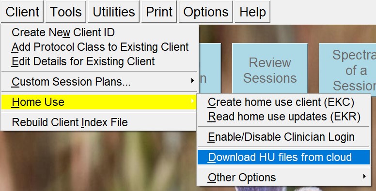
Download HU file from cloud 53
Check status of EEGer remote use USB memory stick (deprecated) 54
Request telephone update of remote sessions from clinician 54
EEGer configuration Options 64
Edit boilerplate file for editor use 87
Change review ratio frequencies/ratios 87
Create ANI Biofeedback 2-Channel Key 89
Create ANI Biofeedback 4-Channel Key 89
Request telephone update of dongle authorizations 89
Upload Tech Support Information 91
Buttons for Client Activities 95
Session Screens and Controls 110
Therapist Display Control Popup 120
Game Feedback Display Control Popup 120
Beta/SMR Protocol Displays 153
Appendix 1: How the Feedback process works. 167
Appendix 3: EEGer Computer Performance Settings 175
Appendix 4: EEGer Home-User Instructions & Resource 178
Appendix 5: EEGer Home-Use Operation & Instructions to Supervising Clinicians 186
Appendix 6: Identifying COM Ports 191
Appendix 7: Fixed color codes 192
Appendix 8: Feedback and Reward Modes 193
Appendix 9: Sound controls 195
Appendix 11: Game Initialization Tool 200
Appendix 14: Game Tailoring Options 207
Appendix 16: Protocol Transfer Utility 216
Clicking on “Install Session Plan” brings up a file selection menu: 220
Create Installable Presets from Existing Presets 222
Appendix 17: Remote Flash Utility 225
Appendix 18: Special Startup Options 229
Appendix 19: Tech Support Menu 231
Appendix 20: Study Manager 233
Appendix 21: Common Problems and Fixes 239
Appendix 22: Supported Amplifier/Encoder Devices 243
Appendix 23: Clinician Login on home-use system 246
Appendix 24: HU-file Upload Utility Errors 247
This device is to be used for general relaxation training when used with supported amplifier/encoders.
US Federal Law restricts this device to sale by or on the order of health care practitioners.
Operators of this device are expected to be health care practitioners trained in neurofeedback or technicians trained in neurofeedback supervised by health care practitioners.
When using an EEG sensor, the result of the sensor's slight susceptibility to strong Radio Frequency Interference (RFI) could be to artificially increase the microvolt reading and, in almost every case, to obviously corrupt the raw waveform. By paying regular attention to the display on the PC screen of the raw EEG waveform, it should be possible to readily identify whether or not obvious extraneous artifacts are present or to confirm that the signal is “clean”. If you observe random or increased signal readings unrelated to user activity, move the amplifier/encoder and client away from any radiating device.
You can also test for susceptibility of the active sensors by clipping the three electrodes together and observing the display for non-zero readings or variations. If you are unable to resolve the conditions, contact Technical Support.
Do not mix electrode types. Electrode connections using mixed combinations of metals can lead to incorrect reporting of EEG data.
Do not forget to clean and sanitize electrodes between use. Follow the electrode manufacturer's recommendations.
Ensure that proper connection of the electrodes to the client is made. This is most easily checked by measuring the impedance of the electrodes to the head using some measurement device.
Follow all the instructions in the instruction manual for the amplifier/encoder to be used.
It has been noted that EEG biofeedback (neurofeedback) may engender a “rebound effect” in some clients, i.e., biofeedback training for relaxation may result, sometime later, in an elevated level of arousal, heightened sensory awareness and increased vigilance. This is usually transitory and fades after a short time.
EEGer is contraindicated in clients with the following conditions:
Individuals who are unwilling or unable to understand the general principles and goals of the feedback used. This includes individuals with excessive behavioral problems or low IQ.
Individuals who experience anxiety or other unpleasant experiences in connection with EEG biofeedback training.
Certain individuals may be unable to learn to control their EEG through biofeedback. Therapy should be discontinued if periodic monitoring of therapeutic progress indicates that the client is not learning despite adequate review of instructions for feedback.
Among those individuals who experience a “rebound effect”, some may find it mildly uncomfortable. In some of these cases it may be necessary to alter the level of relaxation being trained or discontinue biofeedback training altogether.
There have been some anecdotal reports of dizziness, drowsiness, fatigue, excitability and/or anxiety associated with an EEG biofeedback session. These symptoms are usually mild and pass within a short time. If they persist, the supervising health care professional should change the training parameters or discontinue biofeedback training altogether.
EEGer4 version 4.4 is a highly modified and updated version of the older EEGer 4.2 and EEGer4 4.3 neurofeedback software. As part of the development process, there has been an extended test process carried out to verify operation of all components of the software.
Significant changes in EEGer4 are:
Improved presentation of feedback games
Advanced support for double-blind studies
Recording/display of operator name
Device monitoring/warning during live sessions
Recording of all settings/options for each session.
Creation of custom session plan. (save them as default session plan on any client)
Display of modification status of session plans.
Additional amplifier options
Additional feedback modes (some experimental at this point)
Home-use clients and sessions
Cloud storage of Keyfiles and Home-use files
As part of the EEGer4 updates, provision for future modes and
capabilities were made.
Support for EEGer4 is provided by EEG Store.
EEGer4 is a software suite designed to provide visual and aural feedback based on electroencephalograph (EEG) brainwave signals. Neurofeedback is used to teach the brain to modulate excitatory and inhibitory patterns of specific neuronal assemblies and pathways based upon the details of the sensor placement and the feedback algorithms used, thereby increasing flexibility and self-regulation of relaxation and activation patterns.
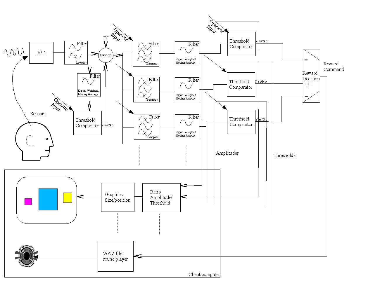
Here is how the feedback process typically works:
The feedback loop begins with the client. Sensors 'pasted' to the client's head pick up microvolt-level EEG signals which are amplified and converted to digital voltages by the A/D subsystem at a nominal rate (usually 256 Hz).
The samples are converted to equivalent peak-peak voltages. All filters in the software are Infinite Impulse Response (IIR) filters. The raw samples are lowpass-filtered to remove 60 Hz ambient noise and threshold-limited to remove muscle (EMG) artifacts. The resulting lowpass signal is fed to a number of 'streams' of processing which are very similar.
In each stream, the lowpass signal is bandpass-filtered into various frequency bands (of the clinician's choice) using IIR digital filters. The filter output is fed to an exponentially-weighted moving average filter which produces a short-term average (peak-to-peak) voltage for further use. The time constant of the averaging filter is selectable but is usually 0.5 seconds. The moving average goes two places: directly to the client (game) software/display and to a comparator. The comparator produces a threshold-exceeded signal whenever the clinician-adjusted threshold voltage is less than the current moving average of the stream.
All the threshold-exceeded signals are processed by the reward decision logic which declares a 'reward' when streams defined as “Inhibit” are all below threshold and streams defined as “Reward” are all above threshold. Rewards are also limited at some rate so that each sound can be separately heard. The reward command is sent to the client computer/display.
The client software logic plays a prerecorded sound file (usually a short beep) whenever a reward is commanded, giving aural feedback to the client that all therapist-specified (amplitude) conditions were being met. The client software also draws simple graphics images giving a continuous (25 Hz) display of the ratio of amplitude to threshold for each stream of data.
The client's EEG response to the aural/visual signals is then sensed and fed back into the loop.
This entire process is shown in Diagram 1.
Diagram 1.
A neurofeedback system is comprised of four components: electrodes (sensors), amplifier/encoders, software, and the computer(s) used.
There are several manuals for EEGer4 users. The Operator's Manual (this one) contains information on all the controls and displays provided by EEGer4. The Technical Manual contains details about the interconnection of data for all the processing, the filter and (supported) device characteristics, and structures of various data outputs. EEGer4 is sometimes just referenced as EEGer.
Typical overall operation consists of
Selecting a client from the list of clients
(Possibly) reviewing the planned session
Beginning a session
Selecting a feedback display (game)
Making adjustments during the session
Post-session, reviewing the results.
EEGer4 has been designed to facilitate this process and automate full data recording.
A “protocol” is the name used to describe the sequence of actions to be used for a neurofeedback session (frequencies, times, site locations, etc.). EEGer provides “Session Plans” as a way of documenting and preselecting the desired protocols.
There are three different “protocol classes” provided by EEGer as a method of organizing similar data. AT class is for Alpha-Theta training data, SMR is for Beta-SMR training data, and EXP is a Beta-SMR-like class where screening and baseline data can be separated from actual training data.
Layouts define what data is presented on a session screen. The layout definitions specify how many traces of information are displayed and the order of the display. Different protocol classes can have differing layouts available. A typical (SMR) protocol class usually has layout selections like these:
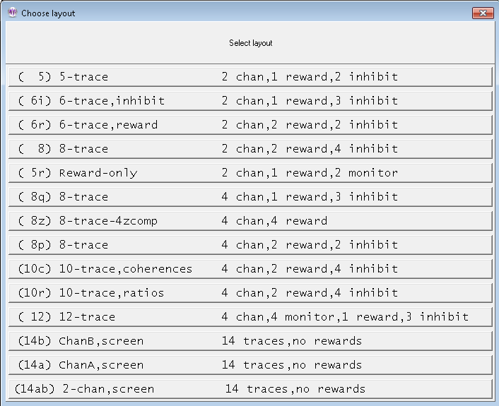
For example, the “5-trace” layout has (from top to bottom) two raw/lowpass input data traces, one inhibit trace, one reward trace, and another inhibit trace. The “6-trace,inhibit” layout has two raw traces, two inhibit traces, one reward trace, and another inhibit trace.
Details of the content possibilities for each layout are contained in the Technical Manual.
Each client has an individual session plan (protocol) for each layout in each protocol class.
Session plan setup is fully described in its own section later in this document.
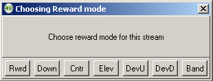
Within each layout, a number of feedback modes are defined. Operators can select from any feedback mode within a layout - but cannot select a feedback mode that isn't already defined within a layout. The selection can change during session (pre-)planning or during a session itself.
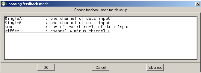
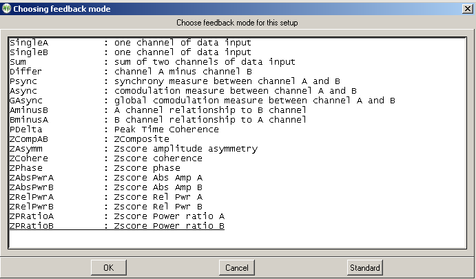
Many of the feedback modes have a selection of reward modes available. The specific reward mode can be selected during session planning and changed during an actual session. Reward modes available of course depend on the specific feedback mode in use but the following is a typical list:
Zscore modes and operation are described in Appendix 12. Zscore is an optional capability provided by purchase and installation of the zscore software from Applied Neuroscience, Inc. (ANI).
Each feedback display (“game”) has a number of options that may be used with it. EEGer provides a large set of options that can be “tailored” for each game on either a semi-permanent basis or for one single session. Examples of this are the sound used for reward occurrences, reward rates, graphics used, colors, etc.
Each EEGer game has a complex set of sound feedback capabilities that can optionally be used. These are described in Appendix 9.
EEGer has a built-in (simple) text editor that operates during sessions (live or replayed) and during the post-session reviews. Data is saved separately for each client.
EEGer has a special remote-use mode for remotely-supervised (home) users. The mode includes features that allow/disallow protocol changes and set time frames and quantity limits for remote users. Also, methods are provided that allow clinicians to login to update/extend/alter the protocol plan for a remote client.
A confidence test of the system is performed as follows:
Start EEGer and observe no errors/warnings reported on screen.
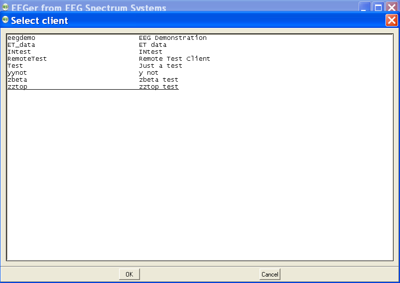
Click on the button labeled “Select Client”
Locate and select “SMR eegdemo” (highlight and click open or double-click)
Notice that the remaining buttons are now available (and the “Select Client” button is now labeled “Change Client”)
Click on “Plan” to verify the current session plan. Click on OK at the bottom to exit the session planning.
Click on “Replay”
When the list of files is displayed, select the “normal eeg” selection (select and click OK or just double-click).
If using an amplifier/encoder with a power setting, turn it on.
Select a game to use (in this case, select Highway).
Verify that there are no error messages on the bottom line of the brainwave display. Error messages (in yellow or red) mean some problem or issue needs to be resolved.
Verify that there is NOT a flashing yellow or red message at the lower right side of the display. Such a message means the amplifier/encoder has not been seen by the computer.
Press F9. If an “Insufficient data” message flashes, wait a little while and press F9 again.
Press F11
Press F5. Notice that the PAUSE message in the lower left changes to RUN
Press F11 once more and listen for reward beeps.
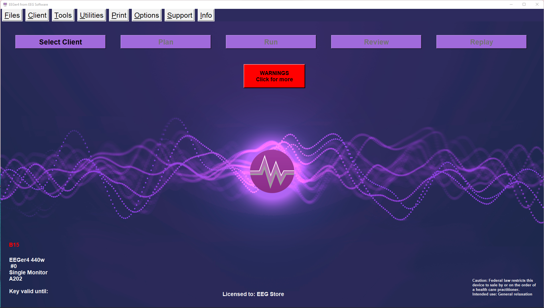
The EEGer main screen as shown below at startup (no client selected). Notice the RED warning message (“Demonstration Only -...”) meaning a successful live session cannot be performed. YELLOW messages are information about upcoming limitations (expiration dates, session counts, etc.). F1can be pressed at any time to show the help file. Also, Alt-Tcan be pressed at the main screen to bring up a tech support menu for aiding in technical support.
There are two rows of selections. The top row consists of Windows-style menus for program-wide actions . The second row is a row of buttons for client-specific actions. Until a client is selected, only the leftmost button (Select Client) is active.
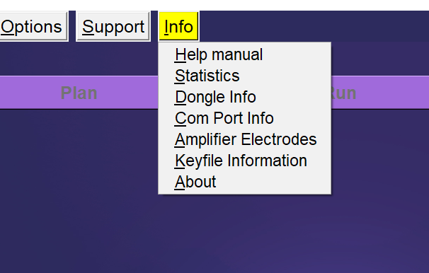
Details of each of the menus listed below are described in greater detail in each corresponding section.
Screens below are the items in each menu with details for each option later in this document.

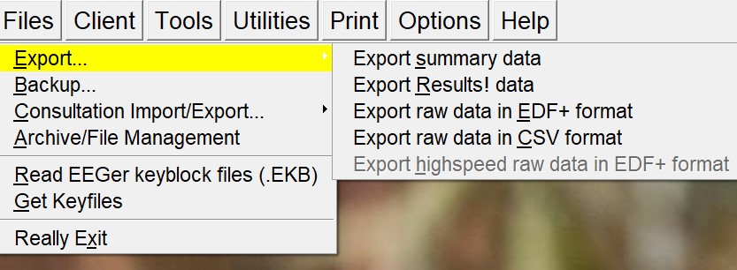
If “Export summary data” is selected, a client selection screen will pop up to allow specifying a client.
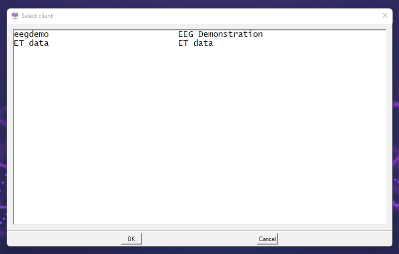
After selecting the client, a window will appear allowing the selection of multiple summary files for the specified client.
When the OK button is pressed, each of the selected summary
files will be exported to the Export directory (default
C:\EEGer\Export). Each file will have the same (basic) filename as
the summary file (identified by codename and a date-number unique
code) but have a CSV (comma-separated-variable) extension. These
CSV files are suitable for direct import/opening by LibreOffice
Calc, Microsoft Excel or other similar programs.
The CSV files have one row of headers and one row for each second of data. Each row has as many columns as are defined in the headers. The structure comes from the layout/trace-count of the data as recorded.
If the
Export Results! Data
option is selected, the client selection window and session
selection is made exactly like the Export Summary Data process
(above) except that the output files go to the Results! directory
specified in the setup configuration. The format of the CSV files
is specific to the Results! Program.
If the Export raw data in EDF+ format option is selected, the client selection window and session selection is made exactly like the Export Summary Data process (above). The output files are in EDF+ format. Filenames are related to the original raw file but have additional letters denoting which set of data is contained in the file. Please contact Technical Support for more information on the content and uses of the EDF+ data.
If the Export raw data in CSV format options is selected, the high spped (256 Hz) data is exported in one-row-per-sample format. If the optional "record fast amplitudes for studies" option is selected (on the SPECIAL configuration options tab or by a study manager), the 256 Hz values recorded during a session of EACH trace will also be output in the CSV file. This makes for very large CSV files.
The optional Export highspeed raw data in EDF+ formatentry allows export of the multi-channel recorded raw data for certain devices if it was recorded during a session.
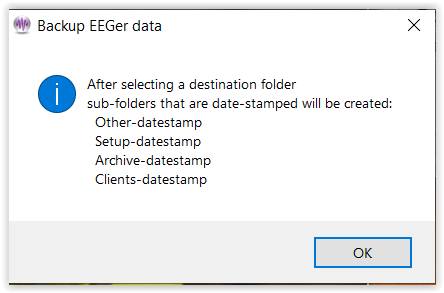
This option is to save/backup EEGer setup, EEGer configuration preferences, client data and archived data. When “Backup..” menu option is selected, a window will popup (shown below) displaying the list of folders backup process will create.
Ideally, it is advised to create a folder of a preferable name at a destination of choice before starting the backup process.
Once, “OK” button is selected, a file browser window
will popup displaying a list of directories from which a backup
folder must be selected. After navigating to the destination
folder, user can selected “OK”.
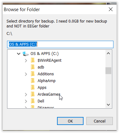
Note: The destination folder must not be EEGer folder in C-drive
If Consultation Import/Export > “Export Consultation data” is selected,
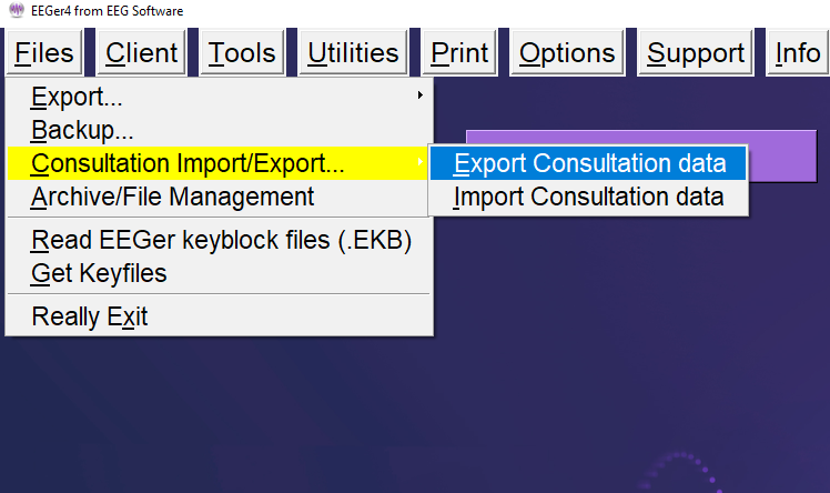
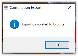
the process is similar to the “Export summary data” process (Export...). The consultation export places a special file (ECE) on the Export (or designated location set in configuration) which can be transferred to another clinician. This file contains all the information needed for another clinician to import and review the client (summary and possible raw) data.
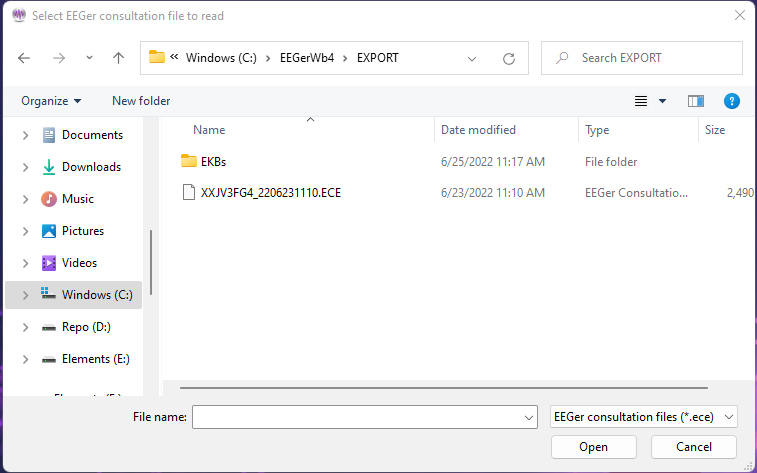
If Consultation Import/Export > “Import Consultation data” option is selected, a file locator dialog will be started to locate and import the ECE file and create a 'client' from the data in the file.
When the ECE file as been selected (double-click or select and Open), a file contents screen will appear:
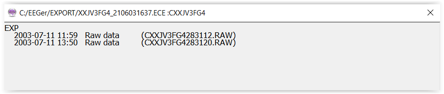
This allows import of only selected files from an ECE file. The user clicks on files (or entire protocol classes) and only the red-marked files are imported when the OK button is clicked.
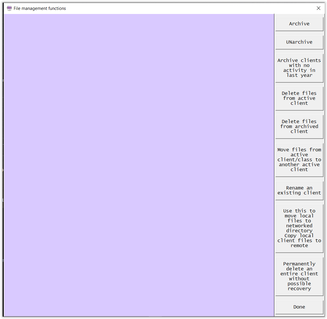
The Archive/File Management selection brings up the following menu:
Archive
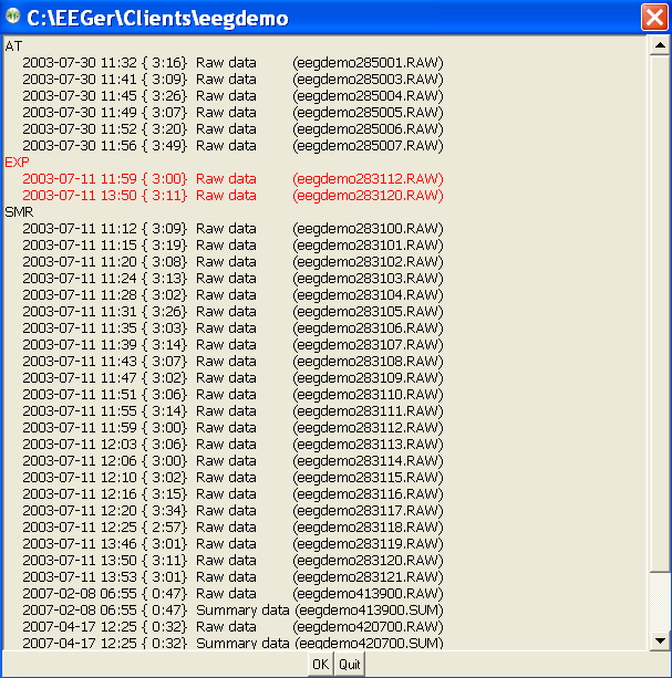
Selecting Archive (for example) brings up the client selection screen:
After selecting a client, the client data is examined and a
selection screen is displayed.
Shown here is the entire EXP protocol class selected. The date/time of each session is displayed.
Clicking on OK causes the data to be archived. This means the data is compressed into the appropriate client-specific .ZIP file and removed from the active client section. If the protocol class item was selected (red), the entire protocol class subdirectory is removed. You need to do this to all protocol classes to remove the client completely from the client list.
UNarchive
When data is UNarchived, the directory and subsidiary files are restored to the current client path along with the data. However, copy of the archived data is left in the archive folder.
The archive/unarchive process is circular. You can archive an entire client, move the archive file to another computer, unarchive it, and have the complete client history, data, and setups available just as if it was always on the new computer.
Archive clients unused in last year
The Archive clients unused in last yearis a convenience too that archives clients with no sessions in the previous 12 months. Of course, clients can always be UNarchived.
Delete files from active client
Individual files can be deleted from current clients (active clients) by selecting Delete files from active client. The process of file selection is common to all the archive functions.
Delete files from archived client
Individual files can be deleted from archived clients by selecting Delete files from archived client. The process of file selection is common to all the archive functions. Note: Deleting client files by selecting this option will make them unrecoverable.
Move files...
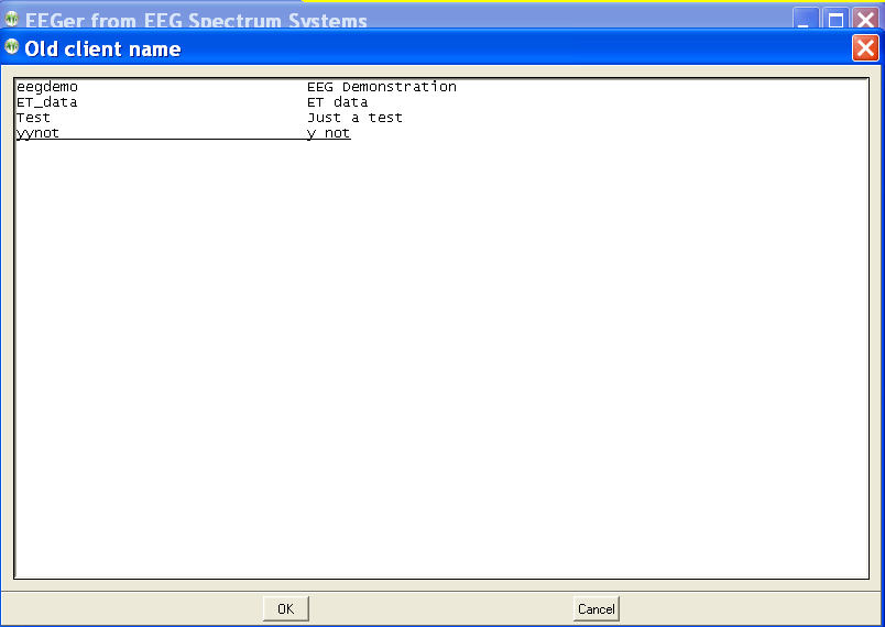
If the Move files option is selected, a source client selection screen is shown:
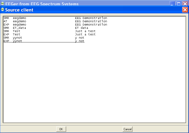
After a client is selected, a selection screen is shown (just like the Archive function above) to allow selecting which files are to be moved.
After picking the files, a destination client selection screen is shown.
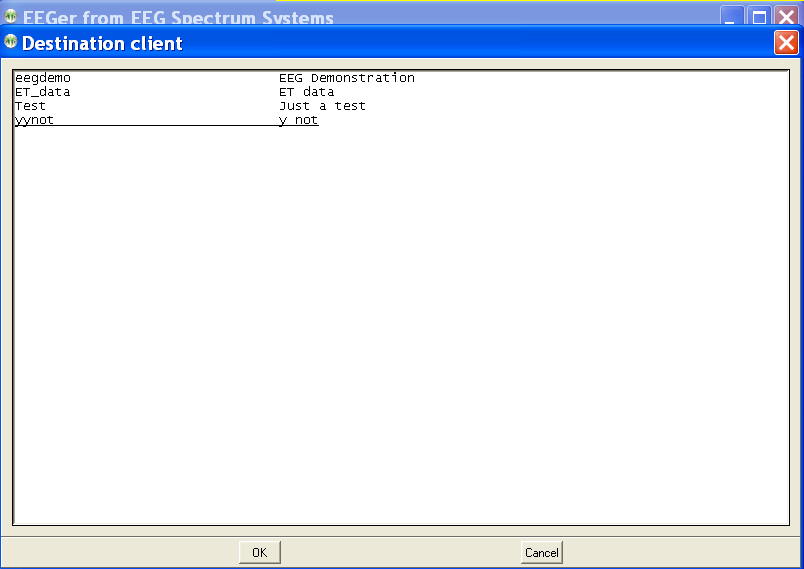
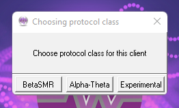
Now a protocol class for the destination client must be chosen.
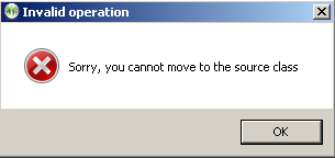
Of course, you cannot move from the same client/protocol class onto itself.
You can move files from one protocol class to another within the same client.
When moving files, the following screen shows the options for the move:
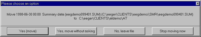
During the move, the source client codenames and fullnames will be replaced by the destination client codename and fullname.
Rename an existing client
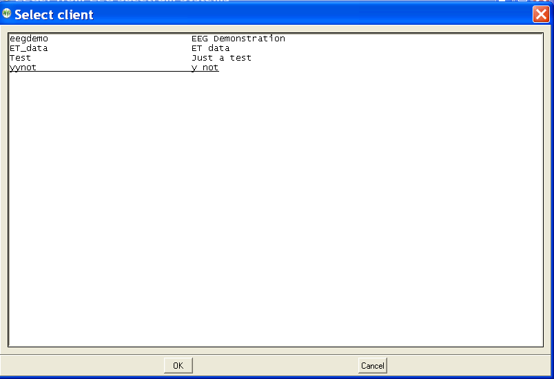
If the Renameclient option is selected, the client selection screen is displayed:
Once a client is selected, a new client name must be entered that does not conflict with any existing client.
Once the full name, birthdate, and biological sex are entered (since you are creating a “new” client), all the "old" client files will be renamed to the new names including internal references.
Use this to move local...
The Copy local client files to remote option exists to handle the case where a remote path for the client data was not available but the clinician went ahead and ran a local session. This option copies local sessions to a remote path specified AND EXISTING in the EEGer options data path configuration. Local sessions are not deleted and copied sessions never overwrite remote sessions (since they are date/sequence numbered).
Permanantly delete...
Permanently deleting an active client can be done by selecting the "Permanently delete ..." option. The next step is to confirm you really want to delete a client forever. THERE IS NO RECOVERY ON DELETED CLIENTS! Perhaps archiving the entire client would be a better option (which also removes it from the active list but makes it available for restoration).
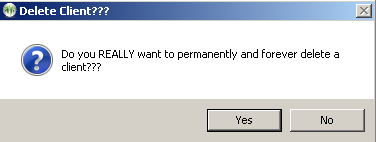
The client to delete is then
selected
followed by another confirmation menu.
Deleting a client this way COMPLETELY and PERMANENTLY deletes the client and all information.
In order to run EEGer live sessions, run other games, use a licensed amplifier, one must have a valid keyfile (keyblock with option and license files) installed. For EEGer to read the license files, select “Read EEGer keyblock file (.EKB)” on the topmenu and a file/folder browser window will appear.
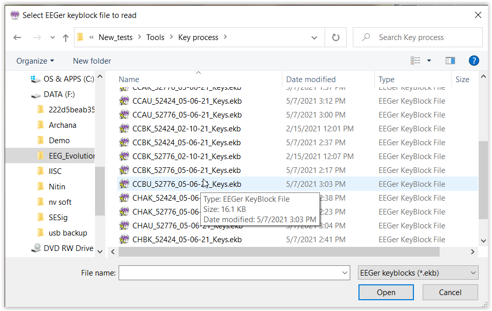
Once a valid EKB file is selected, EEGer will read the information in the keyfile and beupdated. After updating, the user can notice any warning signs (highlighted in red) on the center of the EEGer screen disappearing.
Note: This process manually installs keyfiles. This is usually helpful when the keyfiles are transferredto the EEGer system offline.
This menu option is used to download EEGer keyfiles from the cloud to update EEGer subscriptions, enables and license files. This utility works only when there is an updated keyfile in the cloud. Also, the downloaded keyfile will automatically get installed. Once the process is over, a notification of the status is displayed.
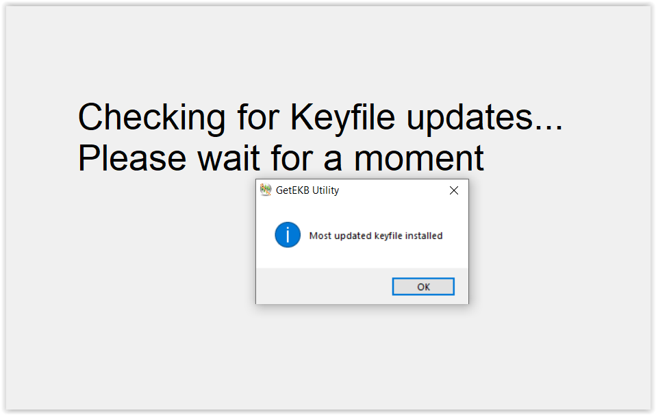
Note: Please refer to Appendix 25: Get Keyfile Utility Errors for all the error messages and resolution step while using Get Keyfile utility
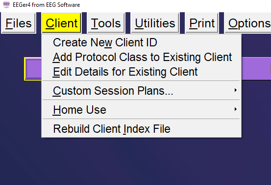
The Clientmenu option brings up a list of client-related actions. Clinician and Home-use systems have different Home-use submenus.
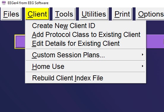
EEGer has the provision to create a “new” client and use the same client name/code for any and all protocol classes (Alpha-Theta, BetaSMR, etc.).
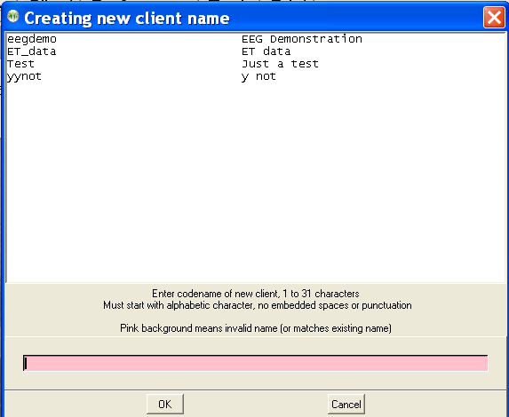
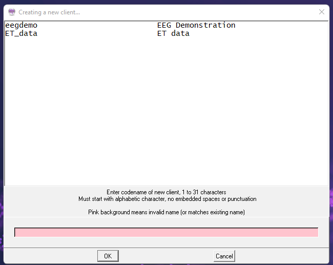
After selecting Create New Client ID, we get the screen below:
Here are shown existing client codes (and corresponding full names). Client codes are 1 to 31 characters with no embedded spaces or special characters (except a hyphen or underscore). The desired client codename is entered into the (initially pink) box. You cannot create a client code name in incorrect format (the pink background will let you know it is incorrect/not allowed).
When you have created a code name, the following window will pop up
to allow entry of a full name:
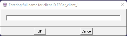
Here you can enter up to 63 characters (with spaces if desired) as the full name of the client.
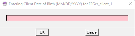
Next, you must enter the birthdate of the client (in MM/DD/YYYY format).
Next you must enter a selection for biological sex:

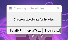
You must then select the first Protocol Class for the new client.
Note: If the first protocol class selected is Experimental, an automatic BetaSMR class is also created.
To use a client for a session, a "protocol class" (like SMR, AT, EXP) must be created for the client. To add additional protocol classes, select Client from the top menu and choose Add Protocol Class for Existing Client.
This menu will pop up to allow selecting the desired client from a list of existing codenames previously created.
After choosing the client (select and click OK or double click on client line), you must choose the protocol class. The protocol class can now be selected from the following menu:
The “Experimental” protocol class allows you to create separate BetaSMR protocol options from normal BetaSMR usage. Note that the data, histories, and reports are separate for each protocol class (although they may be combined using the Archive/Move option). After the protocol class is chosen, the appropriate subdirectory, defaults, etc. are created on the hard drive in the path selected in Preferences.
An option is then given to allow a custom default session plan to be specified for the protocol class.
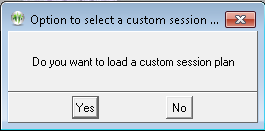
If Yes is selected,
options are given as described in the following paragraph.
"Edit Details for Existing Client" allows editing of a client full name, birth date, and biological sex using the same screens as those used in the initial creation.
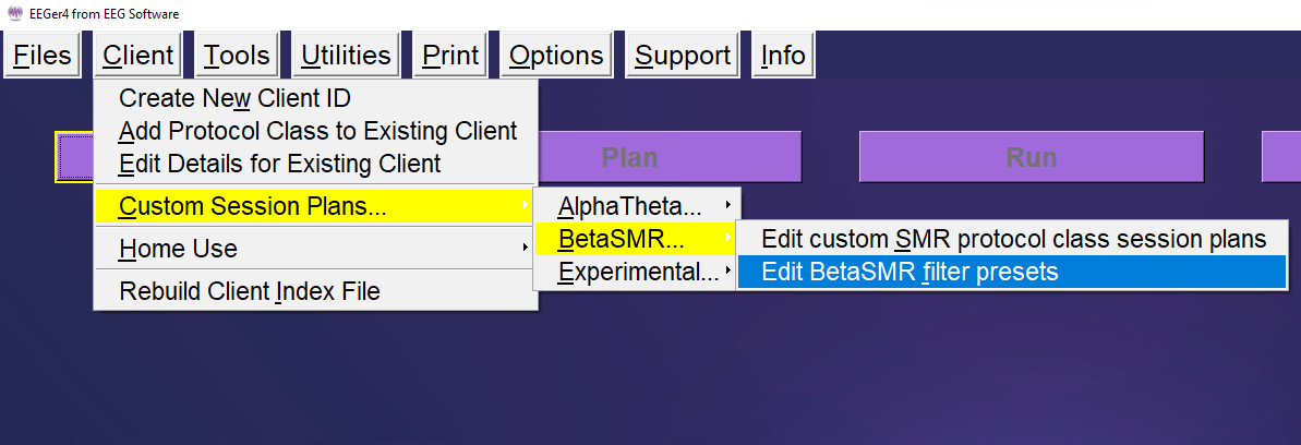
The custom session plans and default filter setups for each protocol class can be edited for each different protocol class.
Choosing Edit custom(protocol class) protocol class session plans
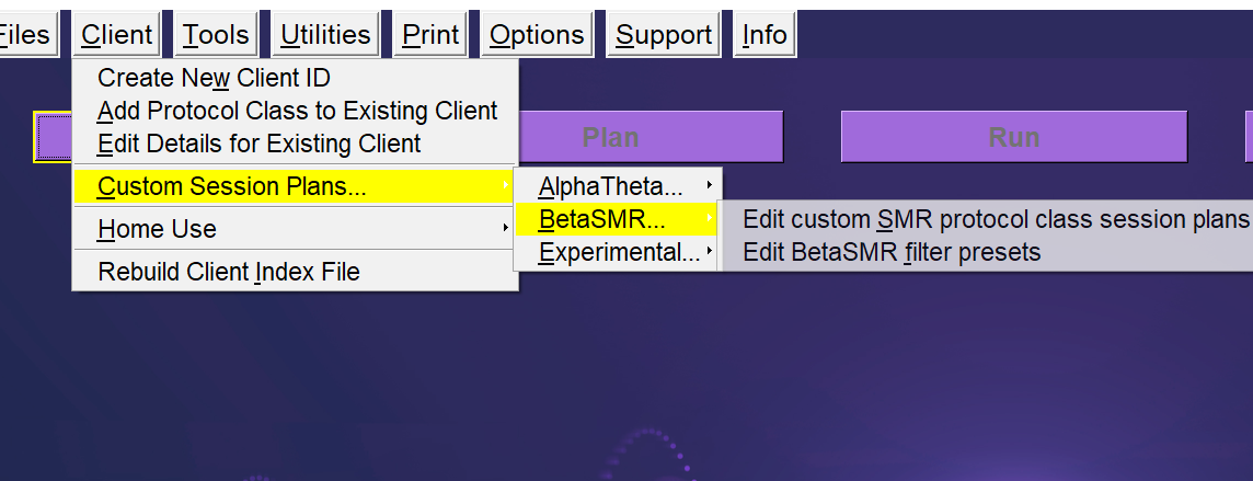
brings up a layout selection menu like this:
Layouts control the session plan and real-time brainwave screen display and processing actions. The “5-trace” layout has two raw traces, an inhibit trace, a reward trace, and another inhibit trace. The “6-trace,inhibit” layout adds a second (low) inhibit processing display/control. This layout specifies that any of the three inhibit streams can inhibit rewards. The “6-trace,reward” layout adds a second reward stream. In this mode, BOTH reward streams must be in a reward state for a score to be given. The “8-trace” mode has two sets of reward+2 inhibits, each driven by a different input stream. Again, BOTH rewards must be in a reward state for a score to be given. There are separate session plans for each layout. There may be additional layouts beyond the four specified above based on certain processing conditions. Layouts are documented in the Technical Manual for further reference.
If there are no custom plans (only the default), the session plan edit screen will be shown automatically.
However, if there are custom session plans, a menu will be shown like this:
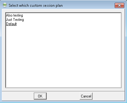
Selecting a plan and clicking OK (or double-clicking) will bring up the session plan edit screen.
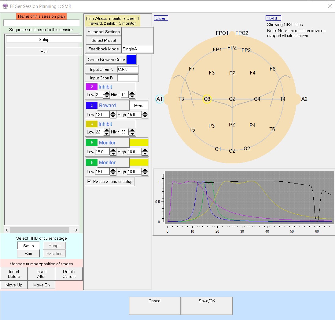
This is almost the same session plan editing screen that is explained later under Plan. The only difference is the field at the upper left titled “Name of this session plan”. During the Plan Session operations, this field is displayed but cannot be changed. This “name” is how the clinician can identify a plan to be chosen. There are some limits on characters to be used (which will automatically not be allowed by the software). This “Name” becomes part of the stored plan name so changing the value implicitly creates a new customized plan.
There are two special cases: a blank name means the 'default' plan; the name “delete” (without the quotes) means to delete the originally chosen plan. It is not possible to delete the default plan. The default session plans are only used when client/protocol classes are first selected The default plan is copied to the specific client/protocol directory if no existing session plan exists. The client's plan can then be modified without affecting the default plan. Each client has a personal plan for each protocol class and each layout.
You can also select Edit (protocol class) filterpresets.
After choosing a layout from a menu as shown for the custom session plan, a screen pops up with existing presets for this protocol class/layout:
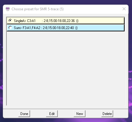
Selecting an entry and clicking on Edit brings up a session planning screen for editing. Clicking on New brings up a selection menu where a default processing mode must be chosen before continuing on to a session planning screen. Only modes available in the current layout are listed.
There may be additional advanced modes available:
The session planning screen(shown below) is limited to one stage. Notice the stage is labeled (“Preset”) and allows creation of a set of filter frequencies, sites, and modes which are selectable from a normal session planning screen.
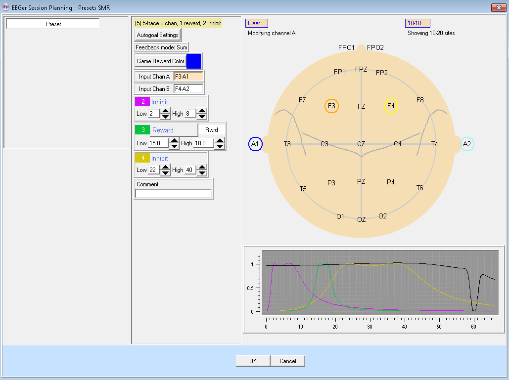
Notice the Comment field. Here you can enter a short description of the purpose of the preset as a reminder. (This will be shown on the preset selection menu.)
Home-use actions are methods by which clinicians can allow clients to train at home and still exercise control over the number of sessions and treatment period. In EEGer, the clinician provides a session plan which is used on a home-use system. The session plan and limitations are contained in an EKC or EKR file which the end user must download and install to run a session (along with an EEGer dongle and license!). A Home-use system must have an internet connection to download these HU-files using the HU-file utility. The Clinician is advised to create multiple Home-use clients for multiple protocol classes to differentiate session plans and protocols (although multiple protocol classes can coexist for a single client). Please refer to Appendix 5: EEGer Home-Use Operation & Instructions to Supervising Clinicians for resources and information on Home-use operation for Supervising Home-use Clinicians. For instruction to home-users, refer to Appendix 4: EEGer Home-User Instructions & Resource for operatingHome-use system.
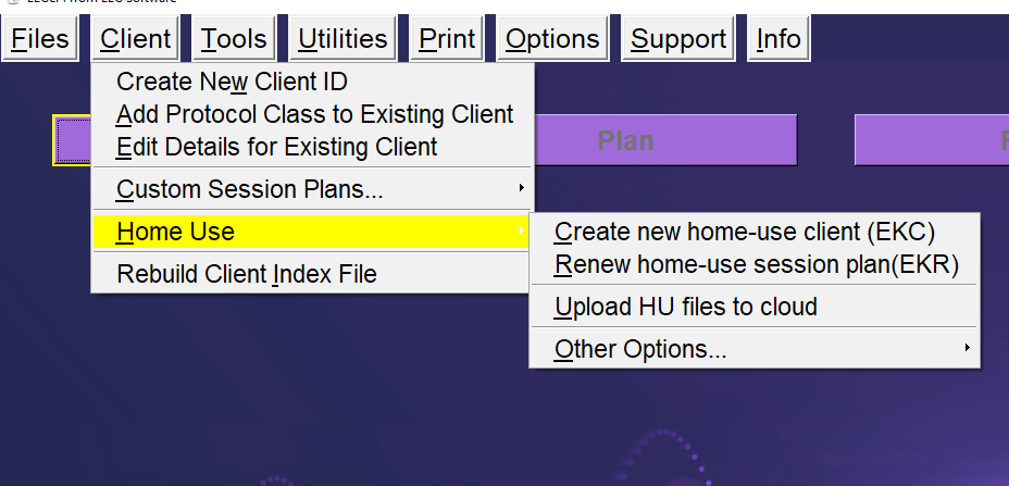
Selecting Create new Home-use Client(EKC) brings up a client selection window.
Then the clinician must select which (already existing) protocol classes to permit the remote user to use.
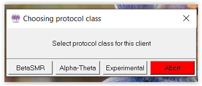
After a protocol class is selected, the layout must be selected. Protocols and layouts may not always have to be the same as the ones used in regular session but must have been previously created.
Each protocol class enable file embeds the CURRENT session plan for the selected client, class, and layout. The limitations must be selected:
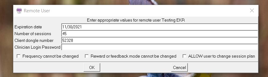
An expiration date is REQUIRED and defaults to 45 days from the current date. The client dongle number must be known (but is remembered once it is entered). Therapist can also enter a login password which will saved in the home-use client file. This login password helps clinicians to perform functions just like in a clinical system that are restricted while running EEGer on a home-use system. See Appendix 23: Clinician Login on home-use system
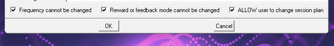
Checking the “Frequency cannotbe changed” or “Reward or feedback mode cannotbe changed” checkbox means that the remote client cannot alter the session-plan setup values during a session. If the “ALLOW user to change session plan” option is checked, the remote user will be allowed to alter the session plan at the home-use computer (and have it used).
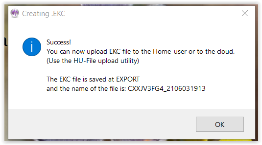
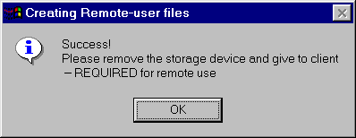
After selecting “ok”, user(clinician) will be sent back to the protocol selection menu. Here, the user can continue to build a home-use client file with other protocols and layouts if they exist. Once done, click on “Finish” button which in green and you will get the following message:
This menu optionis primarily used to update/renew a session plan forhome-use clients. In the event where
a)number of allowed session on home-use system must be increased
or
b)to update the session plan and session limitations
or
c)to add a therapist login password on home-use client,
an “EKR” filemust becreated.
Selecting this option is very similar to Create new Home-use Client (EKC) process. After selecting a client, the protocol class selection screen (and layout screen) will be prompted along withthe same limitationconfiguration screen. Upon completion, the following message will be seen:
This utility is used to upload Home-use files (EKC, EKR, ELS and ELP) to the cloud from a Clinical system for it to be downloadable by a Home-user. Selecting this option will bring up the Home-use upload interface shown below:
Upload:
Clinicians must first upload “EKC” file to be downloaded by Home-userwhich is then later installed on the home-use system in order to start live sessions on a home-use system.
When a home-use client runs out of sessions or needs an update, an “EKR” file is first created and, using this utility, the file is uploaded.
In order to upload any HU-file, the dongle number for the Home-use must be entered in the Dongle Number field. In the File Description field, user can enter alphanumeric characters up-to 60 characters long. Only symbols acceptable by the utility is ‘-’ and ‘_’. File description tag is only used to identify a particular file when multiple files (EKC, EKR, ELS and ELP) are uploaded for a home-use dongle.
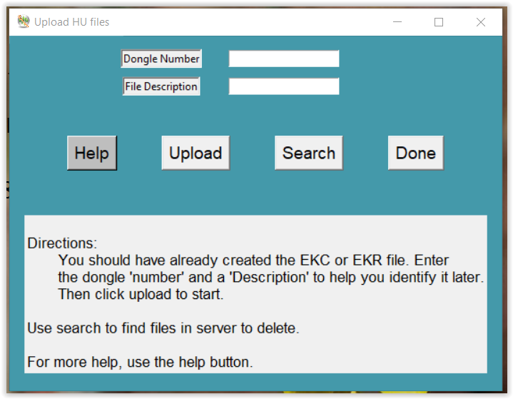
Once dongle number and file description are entered, you can click on “Upload” button which brings up a window to search for HU files (shown below).
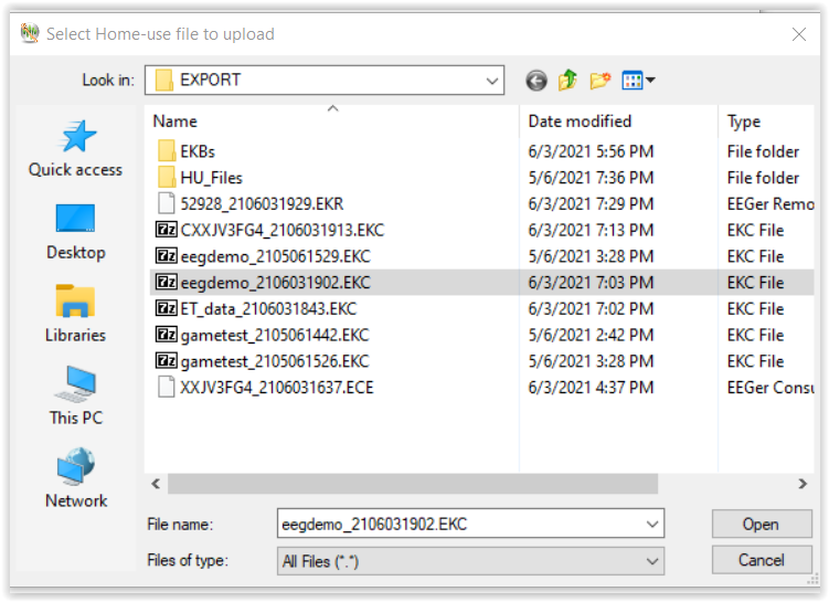
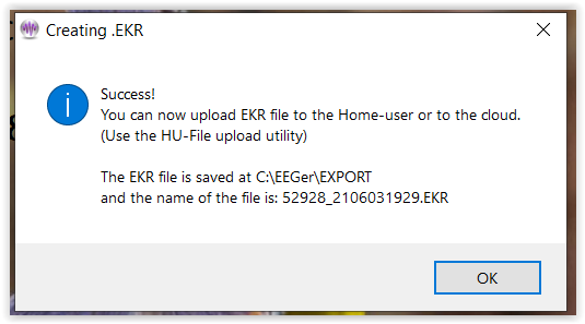
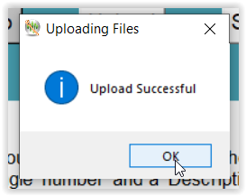
Select “open” when you have located the HU file. When the file successfully uploaded, you will be notified about the status.
Search:
The search option is generally used in two ways.
1. To verify if any of the files uploaded to the cloud/server are still present.
When you enter a home-use dongle number and select “Search”, the utility first verifies if you or anyone from your dongle group have previously uploaded an HU file. If there are files present, a list is displayed like this:
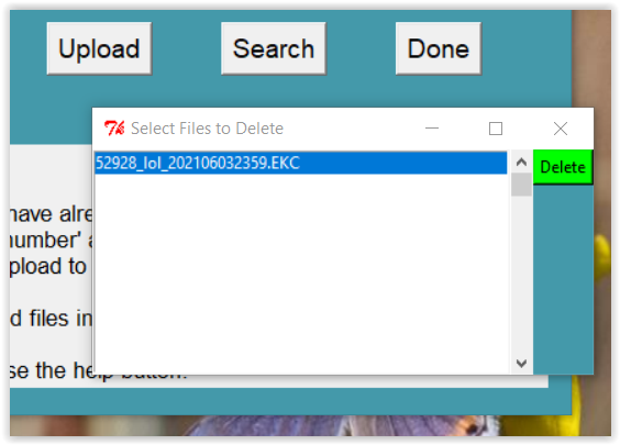
2. To delete a HU file in the cloud.
Just like verifying files in the cloud, a list is displayed. You can select one or multiple files (use Ctrl button for selecting multiple file) from the list and click on the green “Delete” button and a success message will pop up on the screen like this:
O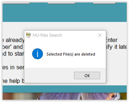
nce you are done, select “OK” button and the utility will
close.
Note: If at any point you think you need more information or help, you can select “help” button and you will get definitions of all the abbreviations and keywords used by the utility.
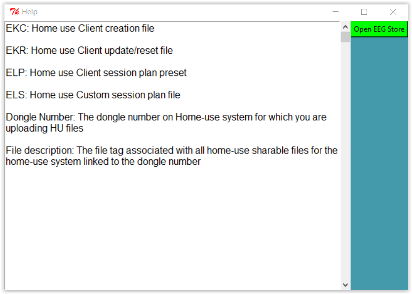
Furthermore, you can select the green button titled “Open EEG Store” to get in touch with tech support on the internet. You can also refer to Appendix 24: HU-file Upload Utility Errors for error codes and resolution steps.
Selecting Initialize EEGer remote-use USB memory stick brings up a client selection window.
After a client is selected, the computer is searched for a suitable storage device. The following menu then pops up to allow the clinician to specify the storage device:
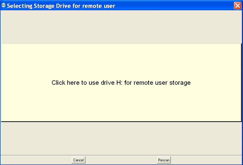
Notice that the H: drive (in this example) contains a suitable device. Also, notice the rescan button which performs another scan (in case you forgot to plug in the USB storage device). A drive is selected by clicking on it.
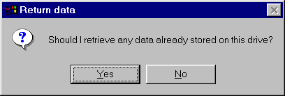
Then the drive is examined for its contents. If it contains a valid EEGer storage device structure and client, a test is made for any data stored on it. In normal use the client would bring the device back to the clinician at intervals (for more sessions or a time extension). At this time, the option of copying the data back from the storage device to the clinician machine is given:
If there is NOT a valid structure/data on the storage device or
after retrieving the data, a cautionary menu pops up:
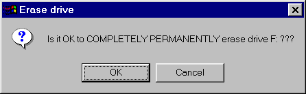
CAUTION: this process really DOES completely and permanently erase the contents of the drive. If you say Cancel, you get a message like this:
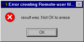
and the process terminates without erasing the storage device.
The device is now initialized with the basic client data. Then the clinician must select which protocol classes to permit the remote user to use.
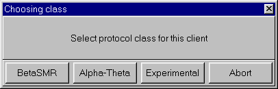
After a protocol class is selected, the layout must be selected:
Each protocol class enable file embeds the CURRENT session plan for the selected client, class, and layout. Once the layout has been chosen, the limitations must be selected:
An expiration date is REQUIRED and defaults to 45 days from the current date. The client dongle number must be known (but is remembered once you enter it). Checking the “Frequency cannot be changed” or “Reward or feedback mode cannot be changed” checkbox means that the remote client cannot alter the session-plan setup values during a session. If the “ALLOW user to change session plan” option is checked, the remote user will be allowed to alter the session plan at the remote computer (and have it used).
The process of selecting a protocol class can be repeated for different protocol classes. Of course, only the LAST selection for a protocol class is saved. When done, press the Done button on the class selection menu and you will get the following message:
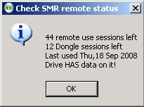
Selecting this option brings up a request to select the appropriate remote use drive.
After selecting the drive, the status of the drive will be displayed in a message box like this:
Selecting the "Retrieve EEGer remote use data from USB memory stick"option will allow selection of the remote device and retrieval of any data on the device just as is automatically done when a new remote device initialization is done (as described above).
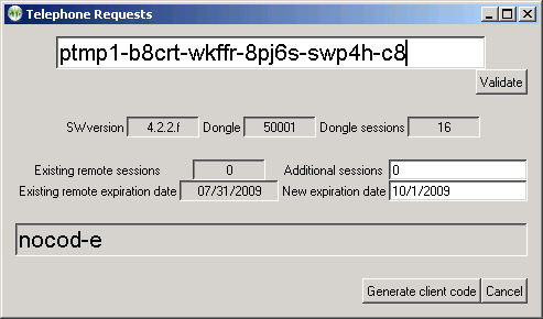
The clinician enters the code from the remote client in the top box. When the entered code is valid (no transposed digits, etc.), the “Validate” button will become active. Pressing that button decodes the data from the user showing how many remote sessions are remaining and the remote session expiration date. Also, the dongle number, number of dongle authorizations (sessions), and the client software version is displayed. Assuming the data was really valid, the clinician can now enter additional remote sessions and/or and extended expiration date. Clicking on “Generate client code” causes a reply code to be generated (the above sample shows “nocode” right now). The 26-character code must be read back to the remote client for entry into the client's request screen.
If the client response was “Failure”, please verify the codes again. It may be necessary for the client to re-initiate the request option and generate a new code (which must then be entered in the top box and the validate button pressed again). You can see if new sessions were added or the date extended.
The client menu on a Home-Use system looks like this:
“Create Home-use client” option is used to initially install a home-use client on a home-use system only for home-use sessions. This process requires an EKC file created by a clinician on a clinical system (refer Create new Home-use Client (EKC)). In order to read the EKC file, Home-use system must have a valid Home-use dongle and its related license files.
EKC file is shared by the clinician either by email or by using the HU-file utility (refer Upload HU-files to Cloud). Before a Home-user can read/install an EKC file, it must be downloaded using the Download HU file from cloud utility or shared by the clinician using other file sharing application (email and etc).
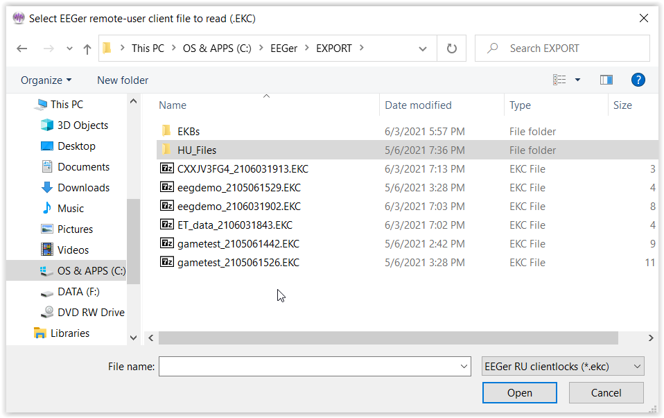
When you select “Create Home-use Client” a file locator window pops up for you to navigate and select the file to be read. If you double click on it or select the file and click on open, EEGer will read information from EKC and will create a new home-use client.
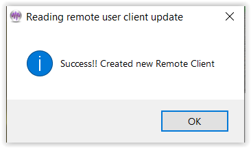
After that a success message is displayed.
Note: If you select an already installed EKC file, EEGer will notify you that the EKC file was already installed. Also, if there are errors during the process of installation, EEGer will provide the error message with an error code.
“Read home-use updates(EKR)” reads the contents of an update file (EKR) created by a clinician which can update/modify number of remote sessions, expiration date, session plan and other session related limitations. This process requires a previously installed EKC file that initializes a home-use client on a home-use system.
The EKR file which must be read on an EEGer home-use system with a valid Home-use dongle and home-use license file. Selecting this option brings up a client selection sequence (if you have not already selected a client). Next, a file locator window where the Home-user must select the downloaded/received EKR file
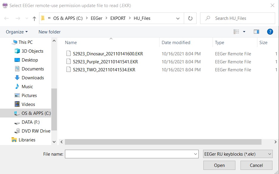
Select and click on Open (or
just double-click) to begin the read process.
Success looks like below. Errors give unique numeric reasons. Common ones are:
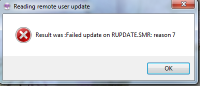
Update already
used
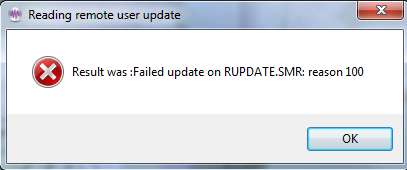
Mismatched dongle
number
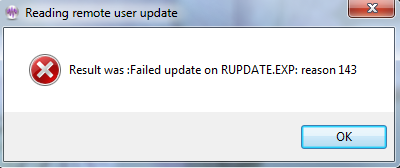
Mismatched client
ID
This feature is used by clinicians to enable restricted features that are only available on a clinical system. Any home-use client on the home-use system can be configured to have clinician login available by entering the password during the process of creating EKC or EKR; see login password for reference.
Before selecting “Enable or disable clinician login”, Clinician must first select the client on which clinician override will be applied. EEGer will bring up window to enter login password like this:
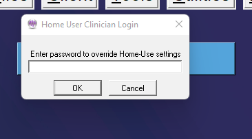
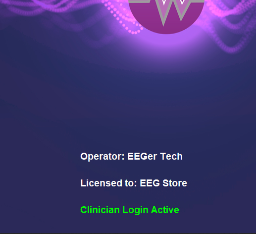
Once you have entered the password and is verified, You can observe a green message saying Clinician login is active.
Note:
You will have 3 tries to get the password right. On the 3rd try, if you fail to type the correct password, EEGer automatically unselects the client and gets you back to the main EEGer screen.
If you select a client and if it does not have clinician login configured or a client that is not a HU client, you will not able able to login as a clinician.
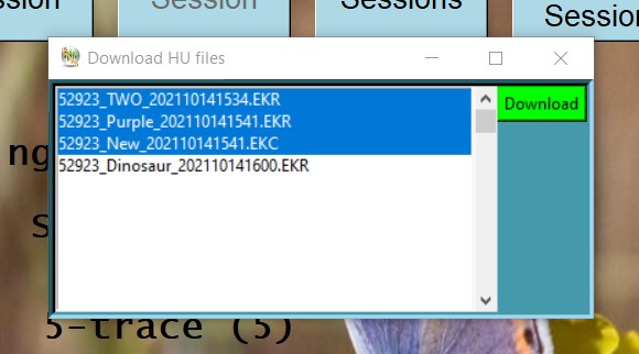
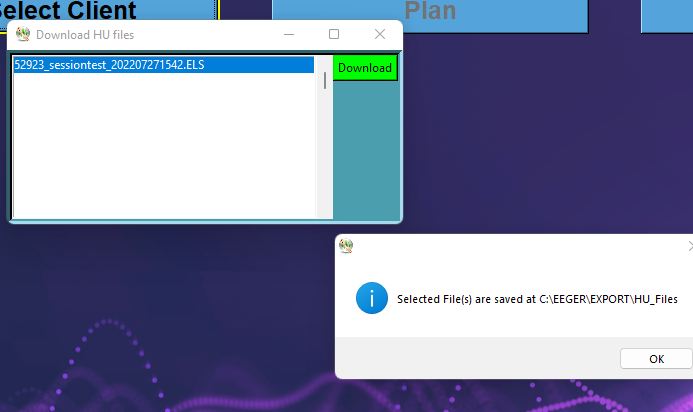
If a clinician has uploaded an EKC or EKR file for the Home-user,
it can be downloaded using the ‘Download HU file from the
cloud’ utility. When this option is selected, EEGer will
display the utility interface which will look like this:
The list of files associated with the home-use dongle will be displayed on the HU-file utility and a home-user will be able to select one or multiple files. Once the home-user has finished file selection, clicking on the green ‘Download’ button to download these home-use files. When these files are successfully downloaded, a success message will be displayed with the location at which the home-use files are saved.
“Check status of EEGer remote use USB memory stick” retrieves data from the remote client USB drive and displays the values. They cannot be changed by the home-user. This function is primarily used to support home-use client (on a USB memory stick) that was initialized on an older version of EEGer (although EEGer 440s and above can also create EEGer remote use USB memory stick).
“Request telephone update of remote sessions from clinician” starts a dialog whereby the remote user can get telephone codes to add additional remote sessions and/or extend the remote session expiration date.
The following screen is used for telephone session updates.
This process uses a time-sensitive code which is ONLY maintained DURING the display of the code values. Closing/re-initiating the process gives/generates different code values.
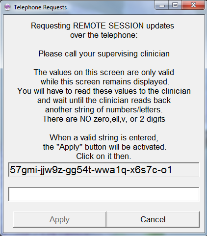
The top set of numbers is read off to the supervising clinician. The supervising clinician enters the character string into a screen on the clinician's computer and creates a corresponding string of 26 characters that are read back and entered by the remote user into the bottom entry box. When a valid string is entered, the “Apply” button will become active. Clicking on it will further validate the data and apply changes. Either a “Successful” or “Failure” message box will appear. Failures are due to incorrect code values.
"Rebuild client index file" is an option to force rebuilding of the client index file. This index is automatically maintained by EEGer but alterations to the client folder outside of EEGer (like manually deleting a client subfolder!) may change the index so it does not match the client data.
You must also rebuild the client index file after moving client files from an older computer to a new computer.
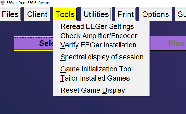
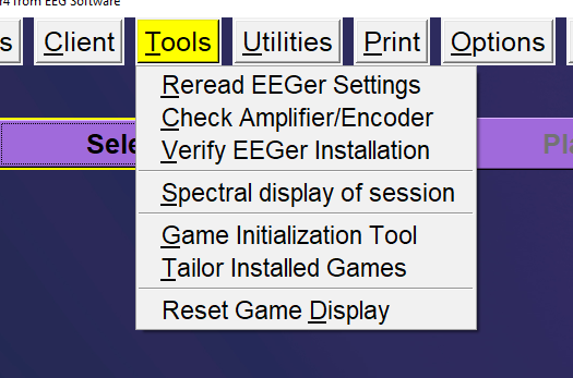
Reread EEGer Settings” will reread keyfiles, licenses and game enables and update EEGer settings and warning messages on the main screen.
Check Amplifier/Encoder”
runs the EIOtest program. This can be used to validate
device operation (or check battery voltages). Further instructions
on the EIOtest
program are contained in
Appendix 10.
"Verify EEGer Installation” examines the required files used for EEGer to confirm that none of them have become corrupted (or missing).
Spectral Display of Session" Analyze session data in spectral distribution (refer Error: Reference source not found).
"Game Initialization Tool" generates a list of installed games and possible options. Note: this must be performed at least once to retrieve any user-installed games. This option only exists in single-computer configurations. The Game Initialization Tool is described in Appendix 11.
“Tailor Installed
Games” allows the user to order the game list, to set
special options, and to create multiple game variations with
different options (described below).
"Reset game computer" just sends a menu reset to the game computer if a 2-computer system. You can see the game screen flicker when it understands this command. In single computer mode or dual-monitor mode, the menu option reads "Reset game display".
Tailoring the game list allows user flexibility in defining games and options for use. Retrieving a game list resets those games and variations whose basic definitions have changed on the game computer (different sound files, etc.). Selecting the Tailor installed games option brings up a selection screen for games to tailor:
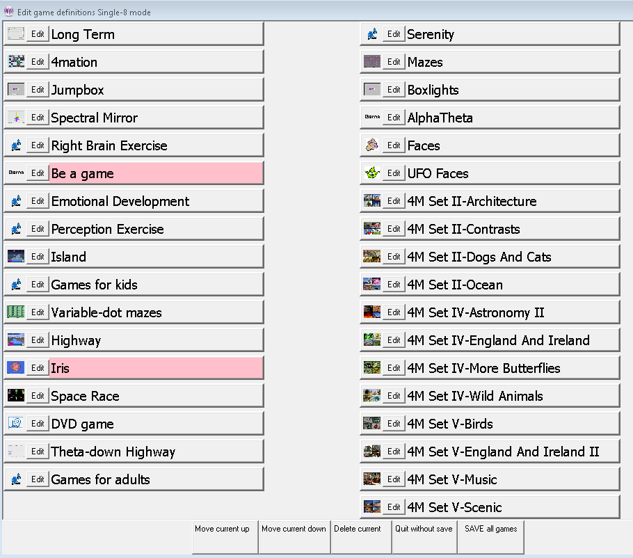
Buttons shown in pink are games that are NOT licensed. They may be only be used in Replay mode for test purposes. The buttons at the bottom allow the game titles to be moved up or down, to be deleted (from the selection list until the next 'retrieve games'), or to be edited.
Selecting the Edit button for a game gives something like this:
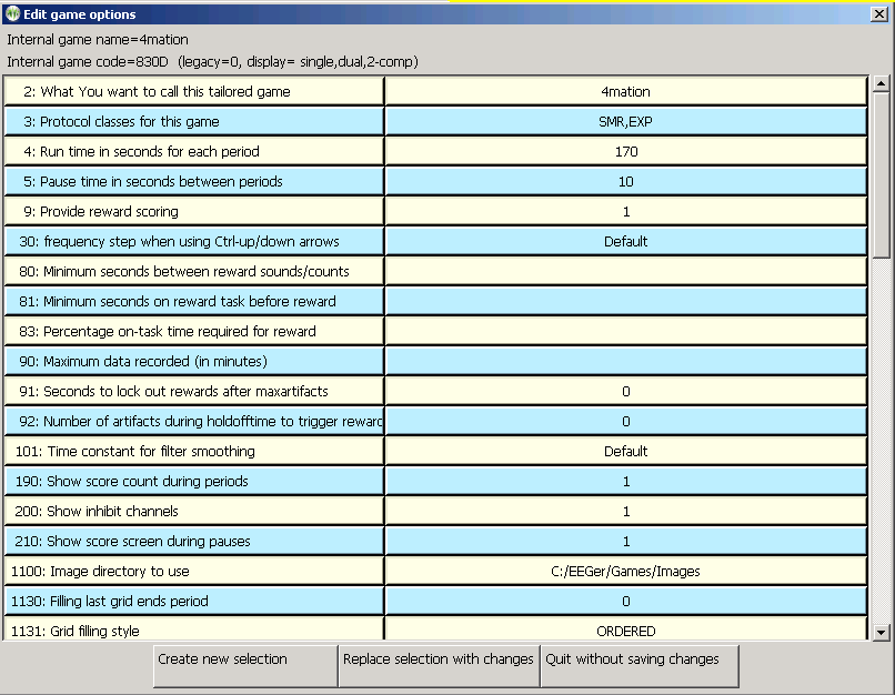
The “What You want to call this tailored game” field is what the “title” of the game will be on the clinician game selection menu. Options can be changed/specified by clicking anywhere on the applicable line. The buttons at the bottom allow modification of this selection or creation of a new selection (hopefully with a new legend and new options) to appear on the game selection menu – just make sure to save with a new name so it will be recognizable on the game menu.
The “Save all games” button on the main tailoring screen saves a new game selection menu for later use in Begin Session or Replay modes.
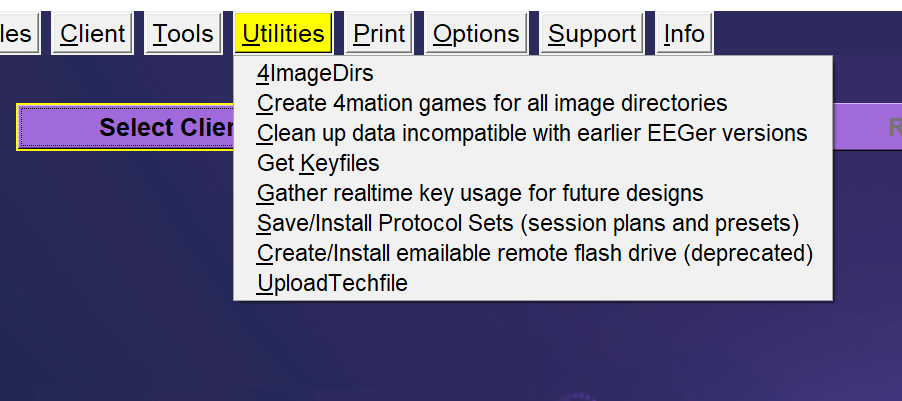
The
Utilities menu item
brings up a list of currently installed utility programs
that supplement the internal EEGer operations. The example shown
below is only the default list of utilities. As other EEGer
utilities are installed, they will appear on this menu.
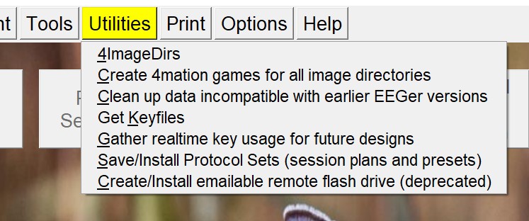
“Save/Install Protocol Sets” displays only if the Protocol
Transfer Utility is installed. See instructions for use in
Appendix 16: Protocol Transfer
Utility.
“Install additional images for 4mation” displays only if the
Image Installer utility is installed. See instructions for use in
the appropriate appendix.
“Create 4mation games for all image directories” displays only if the Add4 utility is
installed. This program adds all the possible 4mation image display
sets as choices on the clinician game selection
screen.
“Create/Install emailable remote use flash drive data (deprecated)” displays only if the Remote Flash Utility is installed. This program allows saving/restoring the contents of a remote-user flash drive under certain conditions as described in Appendix 20.
“Clean up data incompatible with earlier EEGer versions” deletes old unsupported files and EEGer preferences settings from EEGer folder
“Get Keyfiles” is the same utility that is on the File menu (Get Keyfile)
“Gather realtime key usage for future designs” saves all keystore menu options used during session for future use. (no clinical or functional significance for this utility)
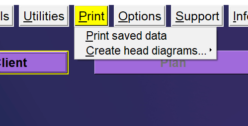
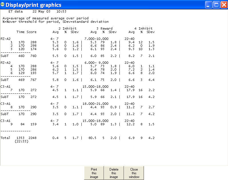
The Print menu item brings up the print manager screen to allow preview/printing/deletion of various graphical/textual outputs of EEGer.
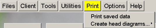
The print manager screen:
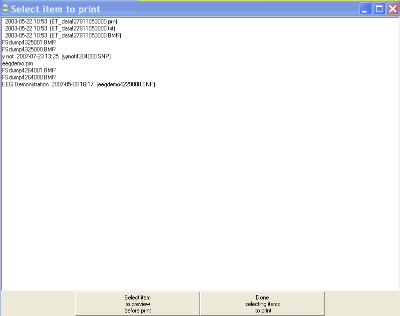
Double-clicking on one of the print menu items brings up a (preview) display screen with several button options (as shown in the sample below).
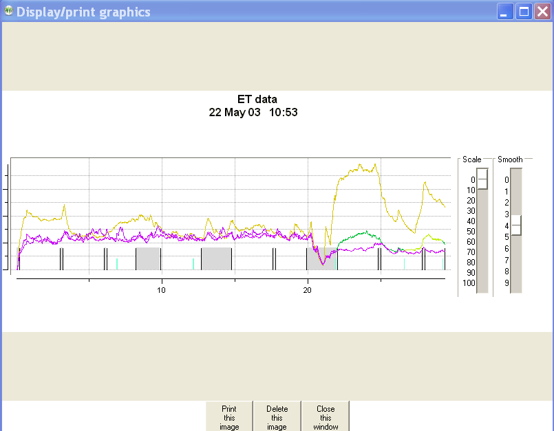
The Print button sends the printout to the current default Windows printer. The Delete button deletes the current file and returns to the print menu. The Close button just returns to the print menu (leaving the file still there). There may be more than one output file for the summary outputs (one for the graphics and one for the tabular data).
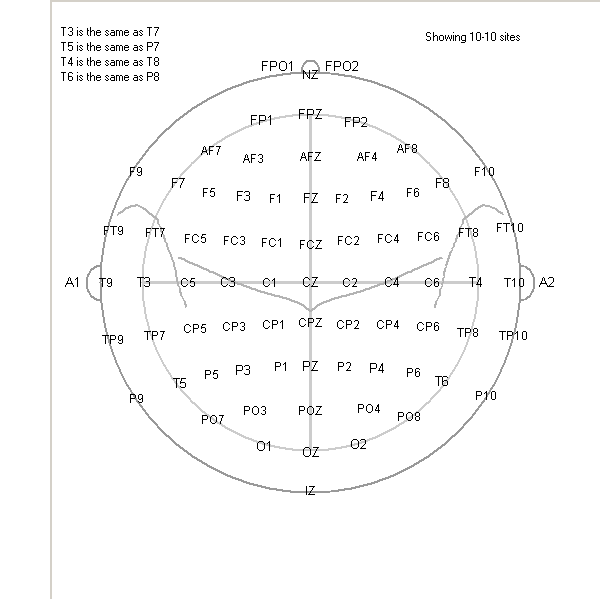
The Create head diagrams option under Print allows the saving of standardized 10-20 and (modified) 10-10 electrode placement diagrams in the print directory.
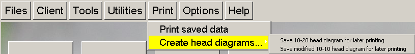
They are printed using the same Print saved data method previously described.
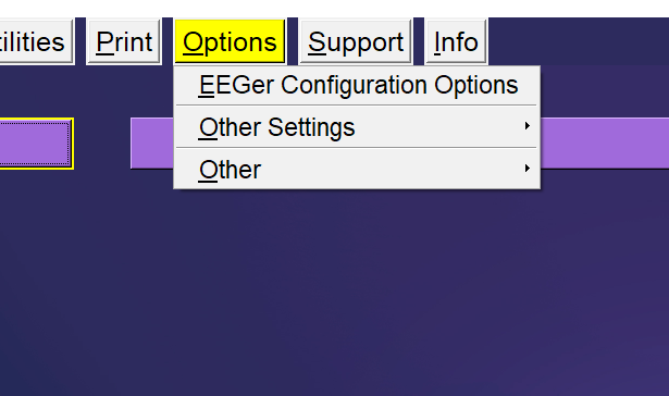
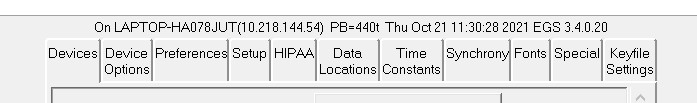
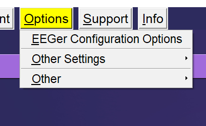
The EEGer configuration Options preference dialog brings up a screen with a number of tab-selected subsidiary screens. Most settings will work for all users. Some changes may have to be made on the Devices tab depending on the amplifier used with EEGer.
Above the tabs is shown some data to help identify any problems. The software version (430b in this sample), the computer name and numeric address, and the current date/time are shown.
The Devices tab controls basic input and operations.
The Device Options tab controls options for selected data input devices.
The Preferences tab contains general EEGer preferences.
The Setup tab contains initial EEGer preferences.
The HIPAA tab contains general EEGer preferences.
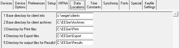
The Data Locations tab selects the data and archive paths.
The Time Constants tab allows changing the smoothing time constants for display and averaging.
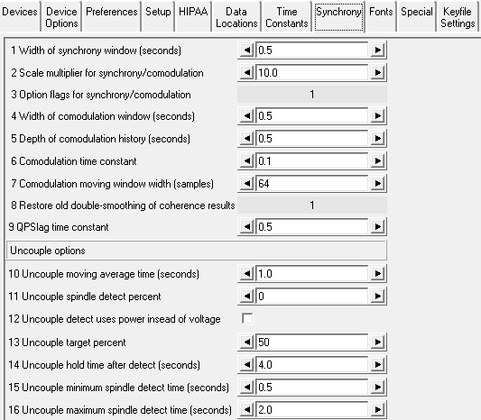
The Synchrony tab allows inspection/alteration of synchrony and comodulation settings.
The Fonts tab allows inspection of the current font settings.
The Special tab allows inspection/alteration of some user options as prescribed by Technical Support.
The Keyfile Settingstab allows inspection (only) of the various licensing/enabling files.
The Devices tab controls which connections are to be used for communications/data sampling.
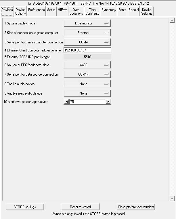
“1 System display mode” selects the mode of operation of the user
interface. Changing this option requires an EEGer exit
and EEGer
restart.
“2 Kind of connection to game computer” selects the particular interface style used to communicate with the game computer. Only used for 2-computer operation.
“3 Serial port for game computer
connection” allows
the choice of a serial port. Only used for 2-computer
operation.
“4 Ethernet Client computer address/name” accepts either a name or (dotted IP) address of a Client computer if Ethernet style connection is desired. Only used for 2-computer operation.
“5 Ethernet TCP/UDP port(integer)” allows selection of a port to be used for Ethernet connections. The default value is 5510. Only used for 2-computer operation.
“6 Source of EEG/peripheral data” allows selection of an EEG/peripheral data source. This is the type of amplifier/encoder component that is connected (or will be) during live sessions for EEG acquisition. Refer Appendix 22: Supported Amplifier/Encoder Devices for the lists supported amplifier/encoders.
“7 Serial port for data source connection” allows the choice of a serial port. Note that you cannot use the same port for both game computer connection and a data device. Also, only certain devices use serial ports as reported in Appendix 22.
“8 Tactile audio device” specifies
the desired port to use for tactile feedback. Two audio devices
are required for tactile feedback in single-computer
operation.
“9 Audible alert audio device”
selects a sound card to use for clinician audio alerts (from the
session plan).
“10 Alert level percentage volume”
specifies the relative volume used for the alert when played. The
default value is 75%.
The “Device Options” tab contains:
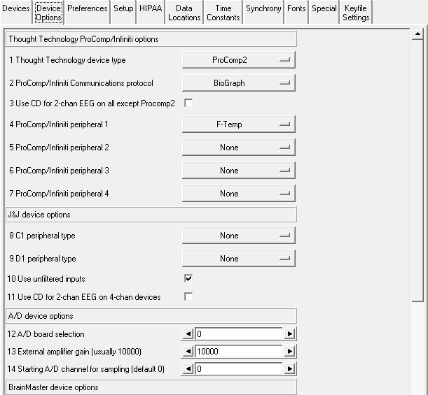
“1 Thought Technology device
type” is a required selection for TTUSB
interface usage since the TTUSB interface does not automatically
detect the correct device type.
“2 ProComp/Infiniti Communications
protocol” allows
either Spectrum or
Biograph communications
protocol to be selected. This must match the switch settings on the
device.
Biograph mode must be used
for TTUSB interfaces (and the device switches set
appropriately).
“3 Use CD for 2-chan EEG on all except
ProComp2” allows
using channels C and D as the “2” channels for 2-channel
inputs.
The ProComp2 cannot process EEG on channels C and D.
“4 ProComp/Infinity peripheral 1”
allows selection of the kind of sensor attached (and how to
interpret the inputs).
“5 ProComp/Infinity peripheral 2”
allows selection of the kind of sensor attached (and how to
interpret the inputs).
“6 ProComp/Infinity peripheral 3”
allows selection of the kind of sensor attached (and how to
interpret the inputs).
“7 ProComp/Infinity peripheral 4” allows selection of the kind of sensor attached (and how to interpret the inputs).
“8 C1 peripheral type” allows
selection of the peripheral input channel (and interpretation of
inputs) for appropriate J&J amplifiers.
“9 D1 peripheral type” allows
selection of the peripheral input channel (and interpretation of
inputs) for appropriate J&J amplifiers.
“10 Use unfiltered inputs” selects
inputs that are NOT lowpass filtered within the device.
“11 Use CD for 2-chan EEG on 4-chan
devices” uses CD
as input instead of AB for J&J devices.
“12 A/D board selection” allows selection of a which A/D board
is to be used. The A/D board selection list must be prepared using
InstaCal™.
“13 External amplifier gain (usually
10000)” allows
changing the gain of the external amplifier used.
“14 Starting A/D channel for sampling(default
0)” allows changing the base A/D channel for
sampling for use with amplifiers having “unusual” wired/programmed
preferences.
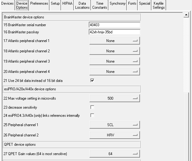
“15 BrainMaster serial number” is
where the serial number of the connected BrainMaster device must be
entered by the user.
“16 BrainMaster passkey” is where the
BrainMaster passkey must be entered by the user. This passkey
allows but does not require dashes between fields and is
case-insensitive. Note: passkeys for use with EEGer are different
than passkeys for use with BrainMaster software.
"17 Atlantis peripheral channel
1" allows selection of the
appropriate input channel (and how to interpret the input) for
Atlantis peripheral data.
"18 Atlantis peripheral channel
2" allows selection of the
appropriate input channel (and how to interpret the input) for
Atlantis peripheral data.
"19 Atlantis peripheral channel 3" allows selection of the appropriate input channel (and how to interpret the input) for Atlantis peripheral data.
"20
Atlantis peripheral channel
4" allows selection of the appropriate input
channel (and how to interpret the input) for Atlantis peripheral
data.
"21 Use 24 bit data instead of 16 bit
data" allows selection of
high-resolution unfiltered EEG
data.
"22 Max
voltage setting in
microvolts" selects the maximum gain setting
for the amplifier.
"23 decrease sensitivity" selects decreasing the sensitivity reported by the device by reducing the LSB of the data.
"24
esiPRO4.3/A400
links references
internally" links both reference jacks together
internally in the esiPRO4.3 and
A400
"25 Peripheral channel 1"
allows
selection of the appropriate input channel for peripheral data (and
how to interpret data).
"26 Peripheral channel 2"
allows
selection of the appropriate input channel for peripheral data (and
how to interpret data).
"27 QPET Gain values(64 is most
sensitive)" allows selection of a
gain control for the QPET device.
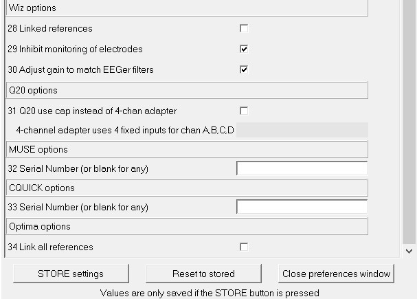
"28 Linked references" allows internal linking of Wiz references.
"29 Inhibit quiet monitoring of electrodes" allows disabling of the continuous monitoring/reporting of electrode status.
"30 Adjust gain to match EEGer filtersI" allows changing the preset gain to match EEGer expected values.
"31
Q20 use cap instead of 4-chan
adapter" allows selection of the Q20 input
channels by the session plan. The 4-channel adapter
uses fixed input channels.
"32 Serial Number" allows selection of the serial number for a connected MUSE device (to aid in matching the Bluetooth device).
"33 Serial Number" allows selection of the serial number for a CQUICK device on a Bluetooth channel.
"34 Link all
references" to link references in 2 or 4
channel Neurobit Optima
amplifiers.
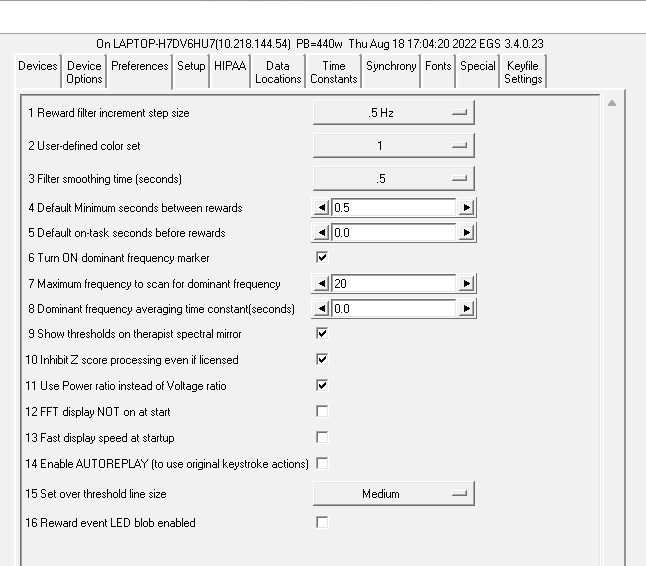
The "1 Reward filter increment step size" of the reward filter center frequency shift can be selected (here it is .5 Hz but .125 Hz (50 Hz set only) and .25 Hz are also available). The step size is automatically 0.1 if either the Dynamic or FIDdll filter sets are used.
The “2 User-defined color set” option allows specification of a custom color set (created using the color changer tool under Options).
"3 Filter smoothing time (seconds)" controls the smoothing time constant for the filters. The default value is 0.5 seconds. The range is .1 to .9 seconds. This value is also controllable in game tailoring.
"4 Default Minimum seconds between rewards" determines the rate at which rewards can be sent to whatever game is currently running. The default value is 0.5 seconds. The minimum value is 0.25 seconds. The maximum value is 30 seconds. This value is also controllable in game tailoring (which overrides this default) and during a session (E popup).
"5 Default on-task seconds before reward" sets how long a client must be in a rewardable state before a reward can be given. The default time is 0 seconds. The minimum is 0.0 and the maximum is 30.0 seconds. This value is also controllable in game tailoring (which overrides this default) and during a session (E popup).
"6 Turn ON dominant frequency marker" turns on the dominant frequency marker at the beginning of the realtime sessions. It can still always be toggled by using Alt-F10. This marker is shown on the FFT and spectral displays.
"7 Maximum frequency to scan for dominant frequency" allows selection of a range of values to scan for a dominant (highest amplitude) frequency. Set to 0 means using the default of 15 Hz.
"8 Dominant frequency averaging time constant(seconds)" allows selection of an averaging time for dominance determination.
"9 Show thresholds on therapist spectral mirror" allows preselection of additional data on the clinician spectral mirror display. This can also be toggled on/off using the clinician display options popup menu.
“10 Inhibit Z score processing even if licensed” turns off zscore computations if performance issues exist. This also inhibits attempts to use zscore in replay situations.
“11 Use Power ratio instead of Voltage ratio” selects which form of ratio rewards to use.
“12 FFT display NOT on at start” turns off the FFT display on the brainwave screen. It can be turned on/off using the Alt-F10 option.
“13 Fast display speed at startup” sets the sweep rate of the brainwave screen to fast mode. The rate can be toggled using the Alt-F12 option during run.
“14 Enable autoreplay of stored data file actions” enables keyboard actions recorded during a live session to be simulated during replay. Pressing any key which changes processing actions turns OFF any autoreplay capability. Note: editor actions are NOT supported for autoreplay since the editor keystrokes are not recorded in the raw data file.
“15 Set over threshold line size” Users can select between SMALL, MEDIUM and LARGE line sizes. This option sets the size of the event line on the wave-screen indicating a particular trace crossing the threshold line during the session.
“16 Reward event LED blob enabled” enables a reward blob on the wave-screen during a live session. Users can observe the Reward blob active on the top right corner when a live session is at a rewardable state.
The tab labeled Setup contains:
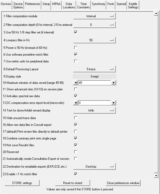
“1 Filter computation module” selects which filter computation method is used. Choices are “Internal” (using the same filter sets as previous EEGer versions), “Dynamic” (using the same coefficient preparation method as the default set) or “FIDdll” (an open-source filter program). Details of the filtering logic are contained in the Technical Manual.
“2 Filter computation depth” allows selection and control of the filters used by EEGer. Selecting 0 as a value means that EEGer uses its traditional internal filter coefficient sets (with 2 stages of data used). Selecting 2 through 5 specifies how many stages of data are used for the filtering operation. 2-5 stages are only usable with FIDdll as filter computation module
The “3 Use 50 Hz 1/8 step filter set (additional memory required)” checkbox allows selection of the internal 50 Hz filter set (instead of the 40 Hz set) but requires an additional 12 MB of memory.
“4 Lowpass filter in Hz” allows selection of the lowpass filter frequency used on all data when the lowpass filter is not disabled.
“5 Power is 50 Hz instead of 60 Hz” selects 50 Hz as the local powerline frequency.
“6 Use software powerline notch filter” enables a software notch filter to remove powerline interference. Some EEG amplifier/encoders do not filter the correct powerline signals.
“7 Use metric units for peripheral data” allows selection of metric units, notably for temperature data.
The "8 Default Processing Layout" is set for 5-trace mode. This default mode is processed during the creation of a new client.
The "9 Display style" is fixed at “Swept”. This option is fixed and cannot be configured in any other style.
The "10 Maximum minutes of data saved (range 45-90)" can be set. This value is used to prescale/preallocate data storage. While a session can go on longer than this time, only this much raw data will be recorded/saved!
"11 Show advanced sites (10-10) on session plan" controls whether the 10-10 or 10-20 site locations will show by default on the "head" displays during session planning. Clicking on the "right" spot on the head will make them show up anyway.
"12 Anti-alias spectral raw data" controls how raw line segments are drawn in the Spectral program. Some video modes/cards require different settings to make the “raw” graphs have a smooth appearance.
The “13 DC compensation error report level” is a value that can be set to provide a (red) warning when the DC offset level correction exceeds a user-input value. If set to zero (the default), no warnings will be given (although the actual DC offset levels are reported on the debug screen).
The “14 Text for Down/Inhibit text display” option allows selection of the text label for down/inhibit training. It is just a label and has no functional changes.
The “15 Hide unused trace data” checkbox determines if currently-unused traces are hidden from view (to minimize clinician distraction). These traces include unused raw, filtered, and FFT displays. This setting can be turned on/off during realtime operation using Alt-F12.
The “16 Allow raw data files in Consult export” option determines if raw data files are selectable for inclusion in consultation files.
The “17 (default) Print review files directly to default printer” option controls whether the Review print buttons save files in the EEGer print directory (for later printing) or send them directly to the default Windows printer. Snap files and screen captures still only go to the print directory for later printing.
The “18 Combine summary print onto single page” forces the summary data printout to be one page. The graphics and text are shrunk to fit and may not be readable.
The “19 Not save Results! files” option disables the automatic creation of Results! files (for use with the optional Results! Program).
The “20 Reserved” option is for future use.
The “21 Automatically create Consultation Export of Session” option causes a Consultation Export of the session just run to be automatically created on the desktop.
“21 Destination for emailable Exports (EKR,ECE,etc.)” allows destination choices for the Consultation Export files, remote user updates, etc.. These choices are: “Desktop”, “My Documents”, or wherever the “Exports” filepath is specified.
“23 Enable < 1Hz notch filter” option enables a high pass filter to block fluctuating DC signals.
The HIPAA tab contains options used to obfuscate the client name. The options make NO alterations to the client ID which is used to identify files, etc. The display mode options are:
All Show the entire full name field
First+initials Show first name and just first letter of later name(s)
Initials Show just the first letter of each name
GUID Show Globally Unique IDentifier of client
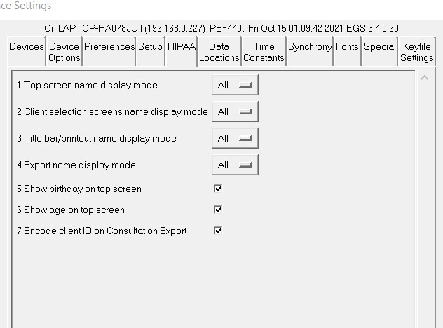
“1 Top screen name display mode” controls the large name on the top screen.
“2 Client selection screens name display mode” controls what you see on selection menus.
“3 Title bar/printout name display mode” controls what shows on window title bars and on printouts (or possible printouts).
“4 Export name display mode” controls what gets exported.
“5 Show birthday on top screen” controls display of month and day of client's birthdate on the top screen.
“6 Show age on top screen” controls display of age of clients that is calculated using the client’s birthdate
“7 Encode client ID on Consultation Export” selects the (default) option to encode the client ID and full name for transmittal over unencrypted internet connections. The encoding is based on the GUID of the client.
The Data Locations tab selects the data and archive paths. THESE PATHS MUST ALREADY EXIST!!! Client session plans, general information, and summary data are stored under the client info path. A separate path is provided for archived (non-active) data. Do NOT use spaces in these pathnames, especially in networked systems. It is better to map to a drive letter in networked cases.
Do NOT attempt to use one of the EEGer clinician machines as a common data repository. During a feedback session on that machine, other machines will be unable to access the data.
When EEGer starts, the existence of the data paths is tested. If not currently available, a message is presented to the clinician informing of the issue. The clinician can continue and run a session locally (after creating a like-named client!). EEGer will internally direct the client and raw data to the internal default locations. The Files->Archive/File Management function has an option to copy the files to the remote locations once they exist - assuming the client code name matches.
The Time Constants tab allows changing the time constants used for display and averaging.
EEGer has been extensively tested using the default time constants. Other values may be used but the user must understand the consequences of making radical changes in these values.
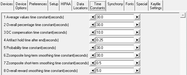
“1 Average values time constant (seconds)” controls the smoothing time for the average values displayed.
“2 Overall percentage time constant(seconds)” controls the smoothing time for the overall percentage value (shown in the upper right corner of the brainwave screen).
“3 DC compensation time constant(seconds)” sets the averaging window for determining DC offset corrections.
“4 Artifact hold time after end(seconds)” sets how long the artifact state is maintained after the artifact event has ceased (to prepare for more artifacts).
“5 Probability time constant(seconds)” controls the smoothing window for maintaining the %over threshold values.
“6 Zcomposite long-term smoothing time constant(seconds)” controls the smoothing window for maintaining the long-term values for the zscore display.
“7 Zcomposite short-term smoothing time constant(seconds)” controls the smoothing window for maintaining the short-term values for the zscore display.
“8 Overall reward smoothing time constant(seconds)” controls the smoothing factor for the overall reward computation.
The Synchrony tab allows inspection/alteration of synchrony, comodulation and uncouple settings.
Please contact Technical Support for information
on any changes to parameters 1
through 9. It
is advised not to change these values without fully comprehending
the working principle of real-time computations.
“10 Uncouple moving average time (seconds)” allows selection of the moving average used for uncouple spindle detection.
“11 Uncouple spindle detect percent” allows selection of percent over average for spindle detection.
“12 Uncouple detect uses power instead of voltage” means use power for detection.
“13 Uncouple target percentage” allows setting the change in threshold for the target trace. The target threshold value will be highlighted when altered.
“14 Uncouple hold time after detect (seconds)”sets how long the modified target threshold is set.
“15 Uncouple minimum spindle detect time (seconds)” allows setting the minimum spindle width.
“16 Uncouple maximum spindle detect time(seconds)”allows setting the maximum spindle width.
The Fonts tab allows inspection of the current font settings.
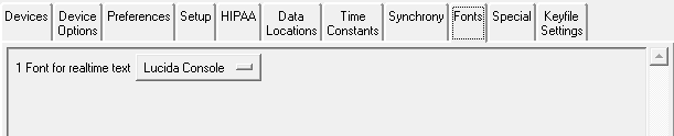
Clicking on the selection menu button gives a list similar to this:
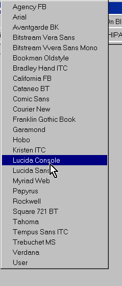
Please note that not all these font selections may not be the most readable or sized to your liking but the choices are yours.
The Special tab allows user selection of some alternative modes of operation of EEGer4.
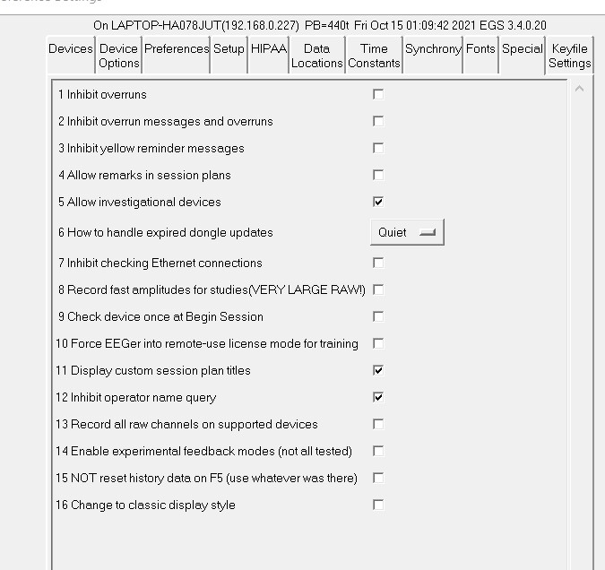
The 1 Inhibit overruns option stops EEGer4 from terminating feedback if the display processor overruns (cannot complete its processing fast enough).
The 2 Inhibit overrun messages and overruns option removes informational messages about overruns and stops termination of feedback on a display overrun.
The 3 Inhibit yellow reminder messages option hides the (yellow) information messages that display at the bottom of the clinician feedback displays. These messages are the class of messages like “Keyboard Lost”, “Not Running”, etc.
The 4 Allow remarks in sessions plans option controls whether the remarks field is displayed (and alterable) during session planning.
The 5 Allow investigational devices option controls whether obsolete and/or devices under investigation can be selected for EEG input sources. Note: After changing this option, the user must exit the configuration menu and reselect it for the new setting to be observed.
The 6 How to handle expired dongle updates option allows selection of the way expired dongle updates are handled:
Message Just display a message
Quiet Don't display a message
Delete Delete the expired update
QuietDelete No message and delete the expired update
The 7 Inhibit checking Ethernet connections option disables the check for a 2nd computer on an Ethernet connection. Checking can be confusing if there are multiple networks present.
The 8 Record fast amplitudes for studies(VERY LARGE RAW) option causes the raw data file to contain high-speed recording of all the running average values.
The 9 Check device once at startup causes EEGer to check for a valid amplifier/encoder during startup of EEGer application. EEGer automatically checks and updates EEGer Configuration Options when the amplifier/encoder connected to the system is identified.
The 10 Force EEGer into remote-use license mode for training allows a clinician to change EEGer operation to match what a remote-license system would be (menus, sequencing, etc.). This mode is intended for training. Changing this mode will require an EEGer restart.
The 11 Display custom session plan titles option displays the title of a (custom) session plan on the top screen.
The 12 Inhibit operator name query option removes the query for the operator name at the start of EEGer. With this inhibited, no operator name will be stored with the data files.
The 13Record all channels on supported device option enables recorded certain device data for all channels while using selected channels for neurofeedback. The data can be exported in EDF for for use by qEEG analysis systems.
The 14 Enable experimental feedback modes (not all tested) option enables all experimental EEG acquisition devices in Devices
The 15 Not reset history data on F5 (use whatever was there) option enables EEGer to continue with the old longtime averages when entering into the next period or resuming session after a pause.
The 16 Change to Classic display style option changes the new top menu layout to the classic top menu style (will look like previous versions of EEGer top menu options)
The Keyfile Settings tab allows inspection (only) of the various licensing/enabling files. Displayed here is the dongle number read in from the hardware, various expiration dates (0 meaning non-expiring), remaining session counts (for session-limited dongles), etc.
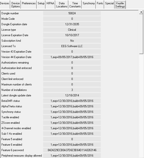
Certain devices require special enable codes (Q20, Muse, Deymed, etc.)
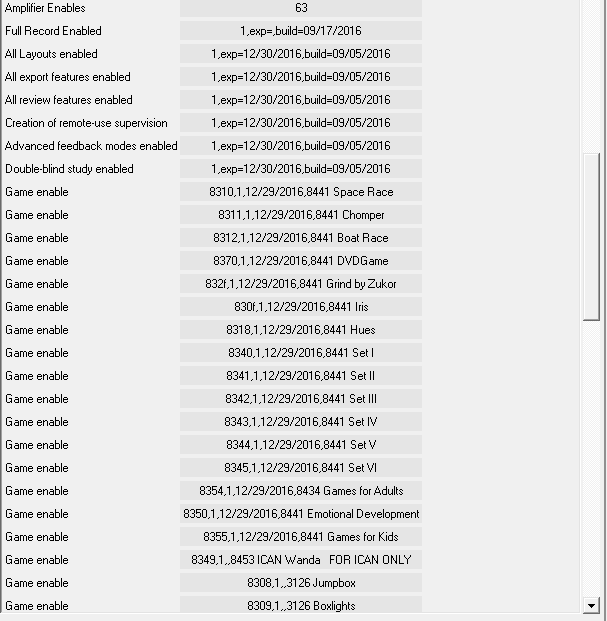
Further down in the same tab are the status of other enables such as game or mode enables. This screen is mostly for technical support.
You can run EEGer without ever changing the default colors. If you prefer different colors for EEGer, you can change the colors used to identify frequencies and some colors for the real-time feedback screen by selecting the Change Colors option of the Options menu.
This screen will then pop up:
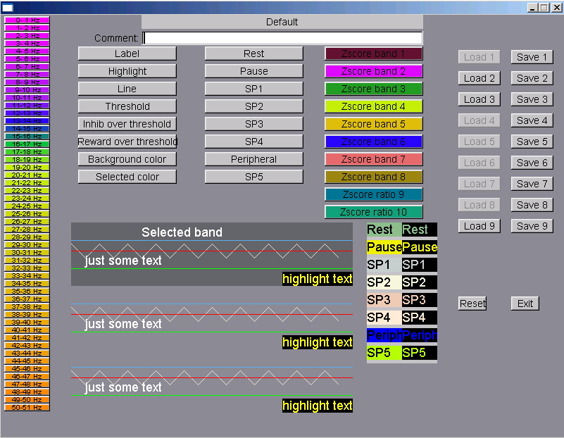
Clicking on any of the left-hand buttons brings up a color chooser window for that particular one Hertz frequency “color”. Clicking on the buttons at the top brings up a color chooser window for that particular real-time color use. The color use is shown by the examples below the buttons. SP1 through SP4 are “spare” colors in this version and are reserved for future use. You must click on the Save button for the specified color set to save the current color scheme for use. Of course, Reset will return you to the default color scheme. The color set actually used is specified in the Preferences settings. Colors 49-50/50-51 have special meaning as they are used by the FFT Highlight option (Alt-F10) described later. Currently defined color sets can be seen by observing the 'active' Load buttons. You cannot load an undefined color set.
Selecting Change background brings up a screen similar to the main menu but with some colored text (and simulated buttons) to assist in determining the readability of the screen in the presence of a background image:
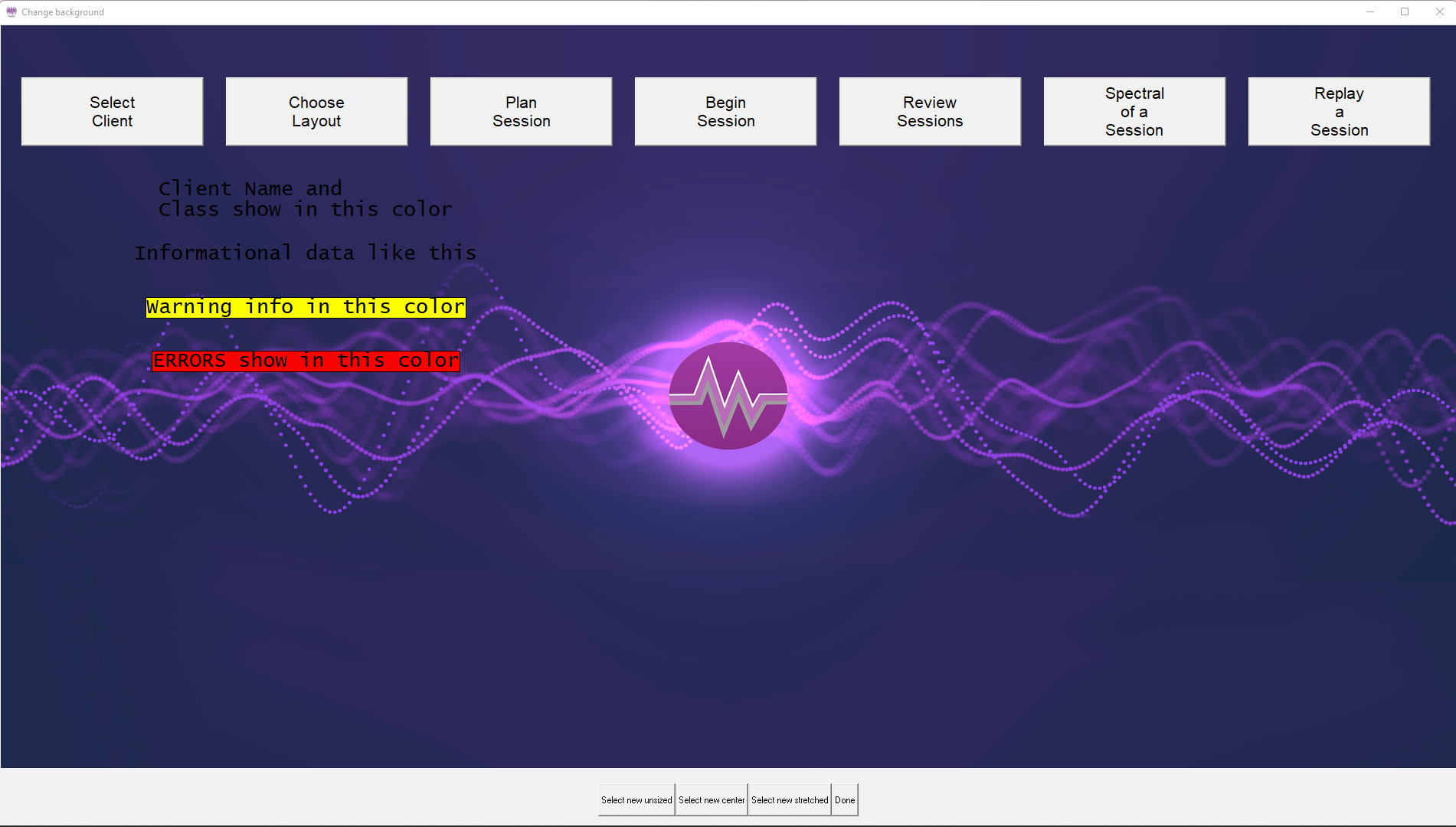
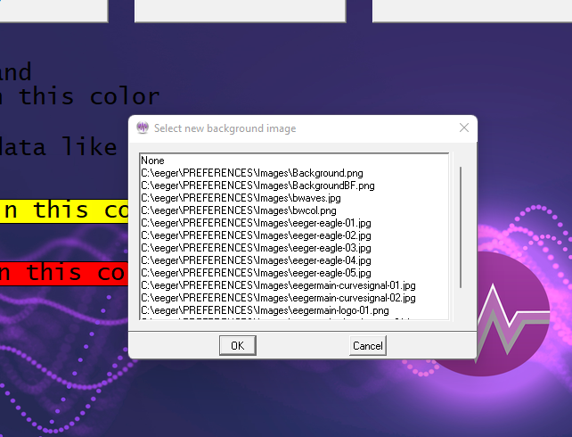
Images to display must be present in the C:\EEGer\Preferences\Images directory. Images can be of any kind that EEGer determines are images (currently .JPG, .BMP, .PNG, .GIF).
There are three image selection buttons at the bottom.
Select new unsized - Select an image and not change size
Select new center - Select and stretch minimally
Select new stretched- Select and stretch to fill screen
When the appropriate image is selected (or None), the Done button saves it in the fastest drawing format for the current screen settings.
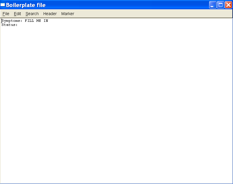
This function brings up the editor to allow entering whatever common data/questions the clinician wants to be entered in the client's notes file (whenever the “Header” button on the editor menu is selected). The editor is exited by using F8, the Files->Exit menu, or the x in the upper right corner.
This option allows a user to customize the Review Ratio option settings.
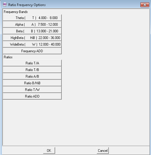
Selecting the Frequency ADD button gives this display:
![]()
![]()
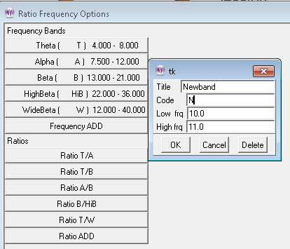
Here a new frequency band (denoted by a name and
letter NOT conflicting with existing) can be added. Selecting the
Ratio ADD button gives this display:
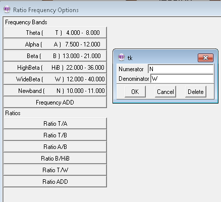
The resulting options are then displayed:
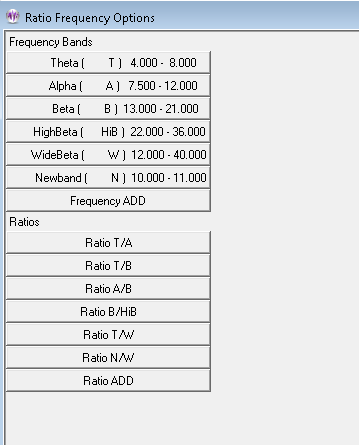
These options remain for later use in the Review
Ratio display/computation.
These options are used to create/enter keys for Applied Neuroscience, Inc. zscore usage.
Details are in Appendix 12: Zscore.
This process allows updating of dongle authorizations using codes (spoken) over the telephone. It is not intended to replace the emailed dongle update process (which has many other options) but only as an immediate method of adding authorizations or extending an expiration date.
This process uses a time-sensitive code which is ONLY maintained DURING the display of the code values. Closing/re-initiating the process gives/requires different code values.
When the process is initiated (by “Request telephone update of dongle authorizations”), the following screen is displayed:
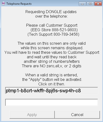
EEG Store must be called WHILE THE SCREEN IS DISPLAYED and arrangements made to purchase additional dongle authorizations. When the 26-character code is read off to EEG Store, they enter it into their program and generate a 26-character response code. The response code must be entered into the blank field. Dashes are automatically put in the correct places. When the entered code is valid (no transposed digits, etc.), the “Apply” button will become active. Clicking on “Apply” will cause the code to be further validated and the encoded changes made. There will be either a “Successful” or “Failed” message box. Failure is caused by an incorrect code (or dongle removal).
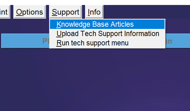
Users can select this option to visit EEG Store’s knowledge base articles. Users can find information about EEGer, keyfiles, home-use systems, amplifiers and for troubleshooting EEGer warnings.
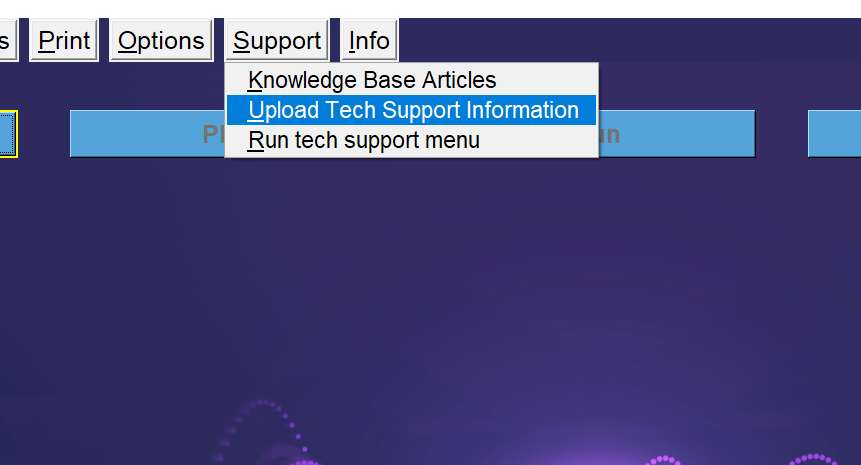
Select this option when you need help with any tech support related issue (will have to contact EEG Store for appointment). This process will generate a diagnostic file for EEG store to fix any bugs or crashes related to EEGer and its utilities.
The "Run tech support menu" option brings up a menu with functions to assist in technical support issues. This menu is described in Appendix (Appendix 19: Tech Support Menu).
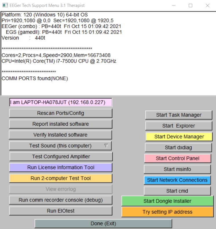
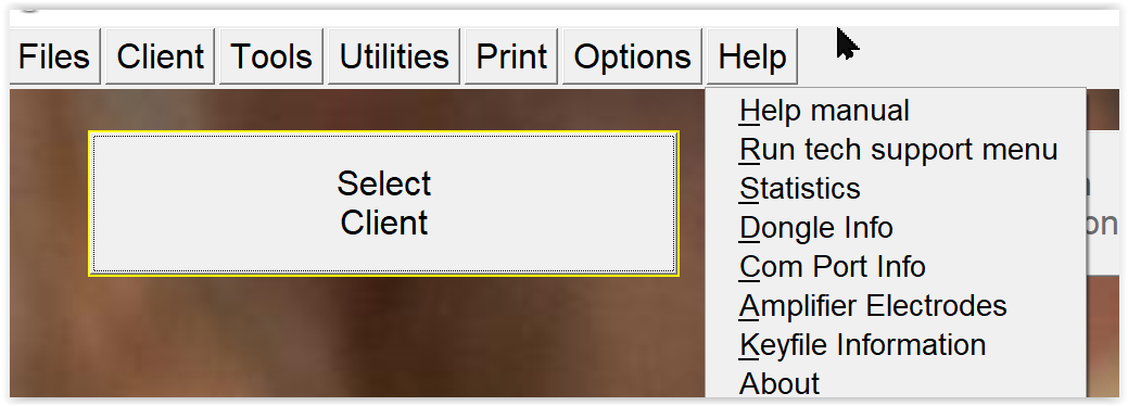
The Help manual contains the same material as in this operator manual. This same data is shown whenever the F1key is pressed.
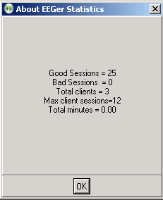
The “Statistics”item
shows a short summary of sessions run (since 4.2.1...) as shown
below. Bad sessions are sessions that aborted for some reason or
another.
The “Dongle Info” display shows some information about the currently-installed dongle.
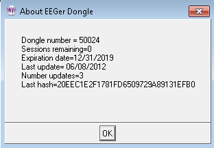
This shows the currently detected communications ports.
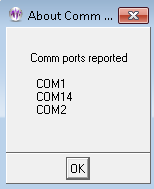
The “Keyfile Information” selection brings up a screen showing the currently installed license and option files. This is primarily used assist Technical Support.
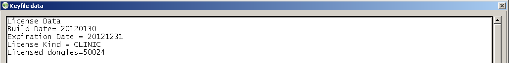
The About screen displays information about the version of EEGer and subsidiary files used.
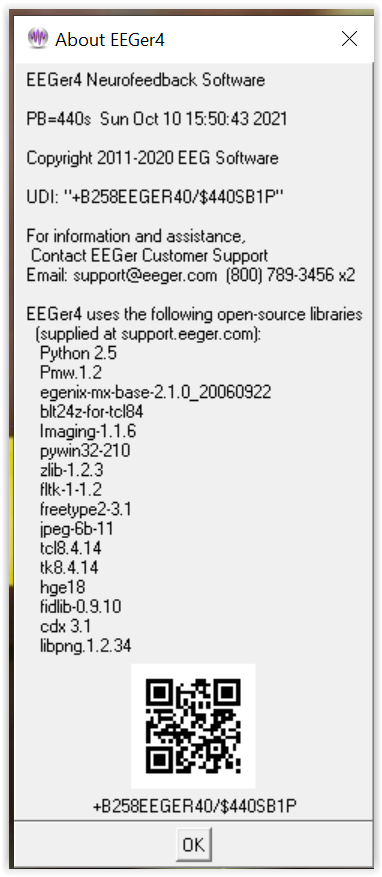
The main EEGer screen prior to a client selection looks like this:
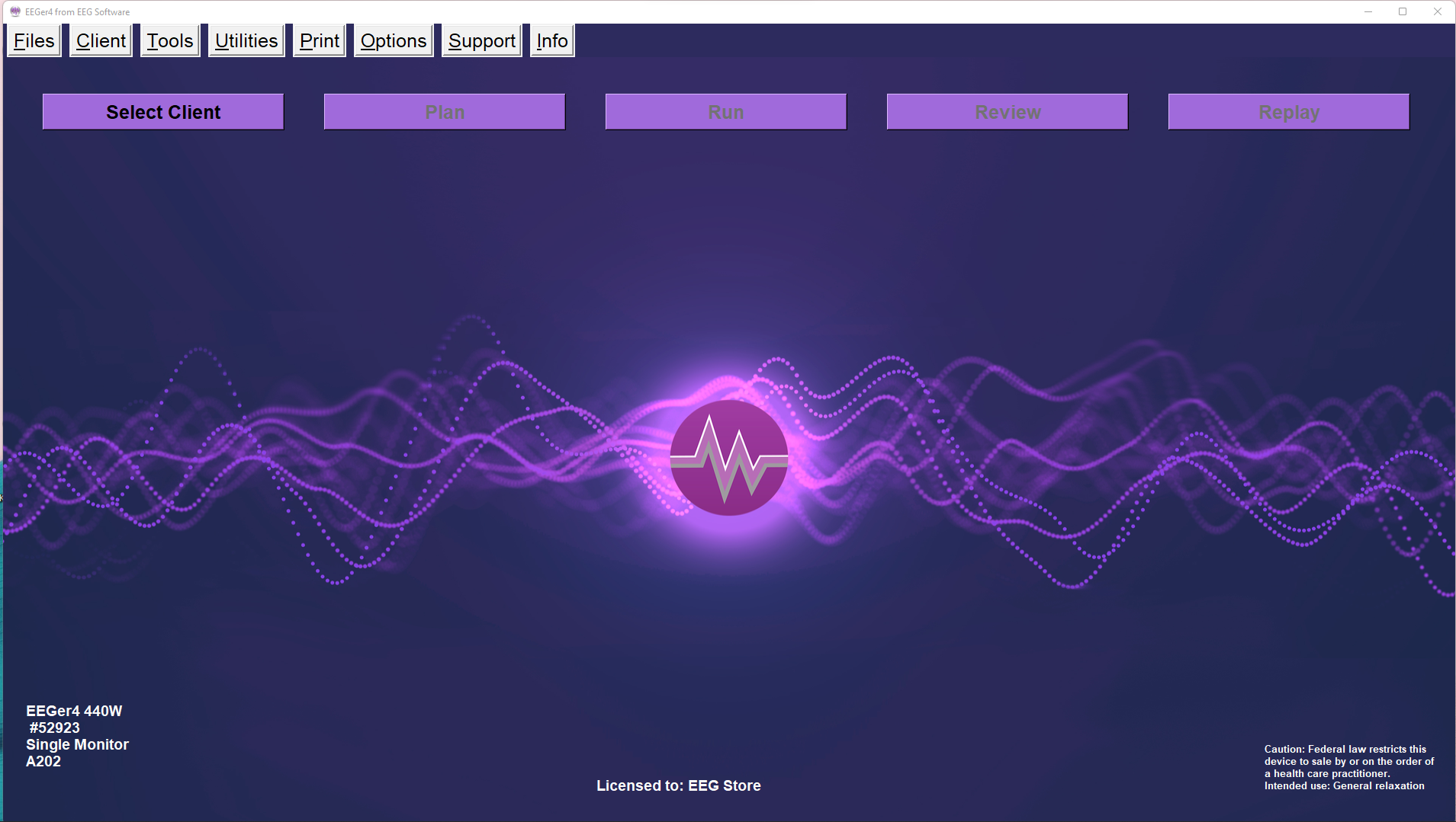
Clicking on the Select Client button brings up the client selection menu with separate selection options to all protocol classes configured to the client:
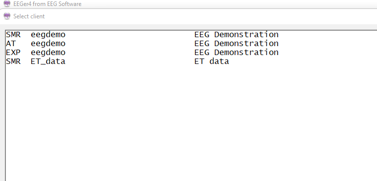
EEGer 440t and higher are backward compatible with home-use client files initialized by older versions of EEGer. On Clicking Select Client, EEGer will prompt either you to either select clients on a USB memory stick or Home-use clients on computer (by installing EKC file).
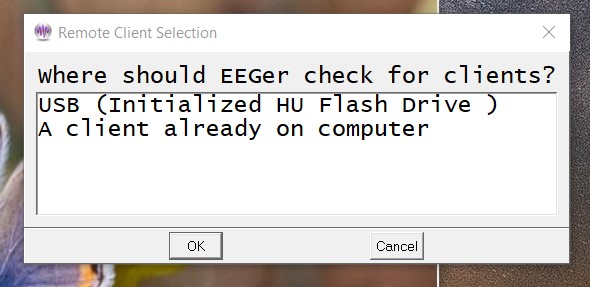
If a home-user selects “A client already on computer”, a client selection menu will be brought up (Menu will just look like the one on clinical system).
Note: If home-user selects “USB”, please follow instructions in Appendix 4: EEGer Home-User Instructions & Resource to select client and follow instruction to start live sessions.
Once a client/protocol is chosen, the buttons become active. Note that the current client, protocol class, and layout are displayed on the top screen. Also, the button formerly marked as Select Client is now labeled Change Client.
Note: Home-use clients cannot use Plan Session to alter the session plan established by the clinician unless enabled by the clinician. Changes made here are ignored when a session is started unless enabled.
Every session requires a "session plan". This is the time/place for changes to initial site locations, frequencies, feedback modes, and autogoal selections are made. Most of these selections are changeable during a session but an initial plan is required. There is a separate session plan for each layout and/or protocol class. A session plan is comprised of a number of “stages”. Each stage will have a particular action/operation such as electrode placement, providing various feedbacks, etc. In this version of EEGer, there are two kinds of “stages”: Setup stages (electrode placement, frequency/mode establishment); and Run stages (actual feedback for a planned time). A plan is saved for each client/protocol class/layout combination (Each client has a session plan for each protocol class created refer to Add Protocol Class to Existing Clientoption). Clicking on the Plan Session button on the main EEGer screen brings up the following screen:
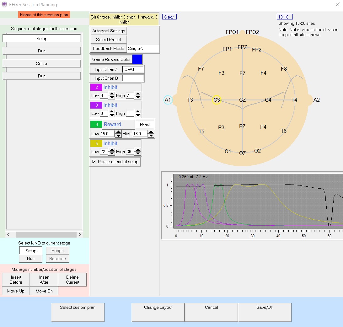
![]()
This display has three “panes”. The leftmost pane is where stages are created or selected. At the top of the left pane is a display of the session plan “name” where blank means the default plan. Any change will prepend an asterisk in this name filed meaning modified from original. Below that is a series of buttons showing which "stage" of a session is being modified. Clicking these buttons “selects” that stage for modification (and changes the display shown in the center and right panes). The bottom of the left pane has buttons allowing for creating and deleting stages or changing what kind of stage it is to be. In the center pane are the values for the currently selected stage. On the right pane (for Setup stages) is a symbolic head diagram with electrode placements and a graph showing the frequency bands (traces) for the current filter frequency settings.
Clicking on the Insert Before or Insert After button adds a new stage with a type of “Empty”.
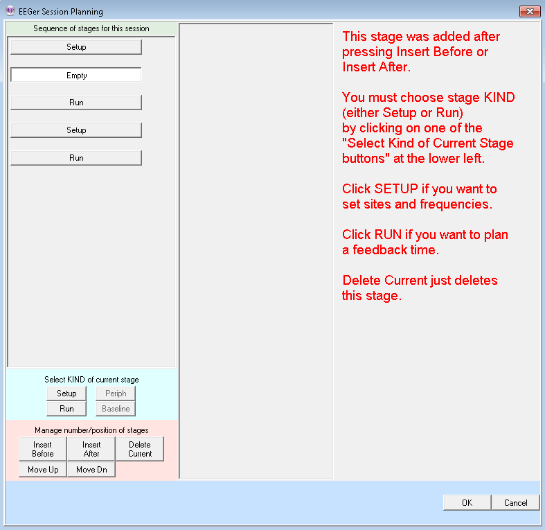
The Empty stage type must be set to a valid type by clicking on either Run or Setup. The Delete Current button deletes a stage (in this case bringing us back to the original screen).

![]()
To change the site locations, you must click in one of the channels
on the Plan Session screen. You can then type in values or use the
mouse to click on desired locations (or the Clear box to reset channel
values). Clicking on the blue box labeled 10-10 (or 10-20) toggles
between the 10-20 placement diagram and the 10-10 (modified)
placement diagram.
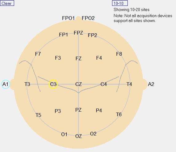
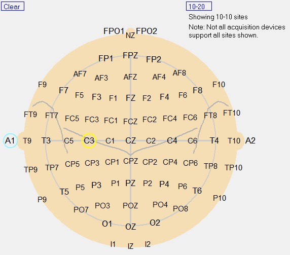
Head diagram with 10-20 site locations Head diagram with 10-10 site locations
Clicking on the Feedback Mode button (top center) pops up a menu of choices for (starting) feedback modes showing all the possibilities for the current layout. It is possible to select a mode at the planning stage (now) that there is no license for. At actual feedback time, any unlicensed condition will cause SingleA (single channel, A input) to be selected. Of course, you can change the feedback mode (using F3 and Shift-F3) during the actual feedback process.
Advanced modes are like these (depending on actual layout selected):
There is detailed documentation of modes in the Technical Manual.
Some common modes are:
SingleA- Single channel, source data from the "A" input channel
SingleB- Single channel, source data from the "B" input channel
Sum- Sum of A and B channels is used as source data
Differ- Difference of A and B channels is used as source data
Psync- Comparison between filtered A and B envelopes (formerly Synchrony)
Async- Comparison between filtered A and B envelope slopes (formerly Comodulation)
GAsync- Comparison between lowpass A and B envelope slopes (formerly Global Comodulation)
AminusB- Difference between filtered A and B envelopes
BminusA- Difference between filtered B and A envelopes
PDelta-Phase difference between A and B signals
RatioA-Ratio of Inhibit band to Reward band(A as source)
RatioB- Ratio of Inhibit band to Reward band (B as source)
RatioAB- Ratio of
A channel Reward
band amplitude to B channel Reward
band amplitude.
RatioBA- Ratio of
B channel reward band amplitude to A channel reward band
amplitude.
D/S-Ratio- Ratio of (A-B) to (A+B)
Unity– Compute 1-|(A-B)|/(A+B) similar toD/S ratioexcept absolute value
There are about 160 modes actually defined. Please refer to Appendix 8: Feedback and Reward Modes
for more details.
Clicking on the Presets button (top center) brings up a selection list of defined presets. These are the values set (changed) from the user-defined presets established as preferences using the Edit filter presetsmenu option in the client menus.
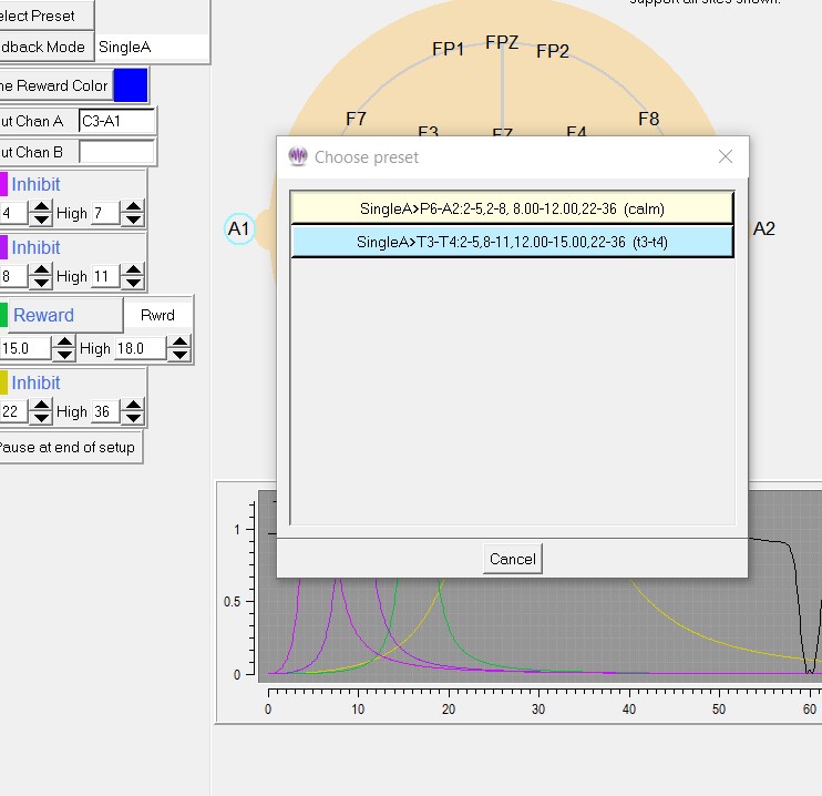
Selection of one of the presets from the list causes the preset-stored filter and site values to replace the current setup stage values and the specified feedback mode and reward mode to be selected.
Clicking on a Run stage button brings up a slightly different screen. Notice there is no "head" shown. The important field on this screen is the run time (Minutes to run). If this value is zero, there is no limit on run time and a manual F5 or F4 will be required to end a particular setup/session. It is possible to select an audio file to be played at the end of the run stage.
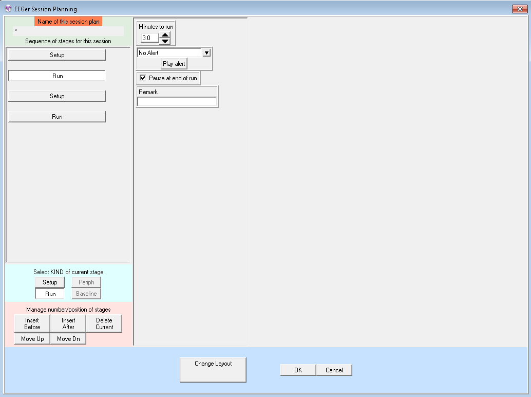
Clicking on Autogoal settings button in a setup stage of the session planning screen brings up a menu which allows adjustment of threshold values used when F11 is pressed (Alpha-Theta example shown). There is a separate set of settings for each setup stage.
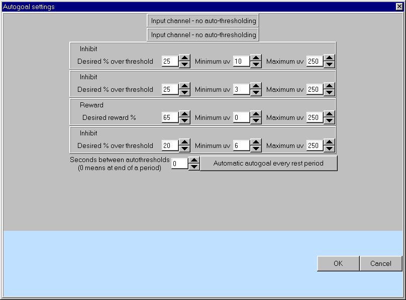
Any stream with 0 % selected will have NO change made when F11 is pressed. The Minimum µv (minimum microvolt) value is the minimum (measured average value) threshold that will ever be “automatically” set by F11. The Maximum µv value is the largest threshold value that will be set by F11. The Autogoal only on F11 button is a toggle where the other value is Automatic autogoal every rest periodor Automatic autogoal every xx secondswhere xxis the number of seconds in the entry box. Clicking on OK saves the autogoal settings and returns to the session planning screen. When the F2 key is used during real-time processing to switch between up and down rewarding, the appropriate percentages would be reversed (i.e. 65% would become 35%).
To change layouts, clicking on the Change Layout button will bring up a layout selection menu.
On the session planning screen, clicking on the OK button saves the session plan and returns to the top menu. Clicking on OK if any field is highlighted with a pink background (marking it as in error) is ignored (and a bell sound is played as an error cue).
This option allows overwriting a client session plan with a customized default plan. First, a client must be selected and a protocol class chosen. Then the appropriate layout must be selected from a list of layouts for the protocol class. If there are NO customized session plans already created, the default session plan for the selected protocol class overwrites the client/protocol class/layout plan. If there are customized plans (created as described in Custom session plans ), a menu similar to this is shown:
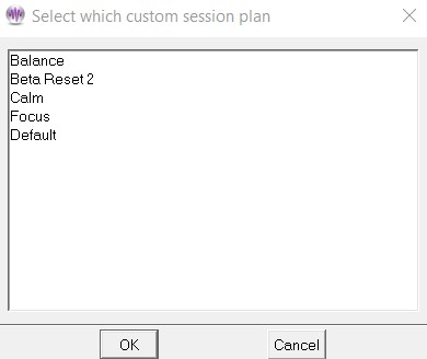
A custom plan can be chosen (by selecting and clicking on OK or by double-clicking on the item). The chosen plan overwrites the client/protocol class/layout plan for the selected client.
This option allows selection of a default layout for a client. The first screen allows selecting a layout from a list of supported layouts.
Next, if the layout has any custom session plan already created, then you will be asked to select a session plan form the list (just like the one shown in the previous section).
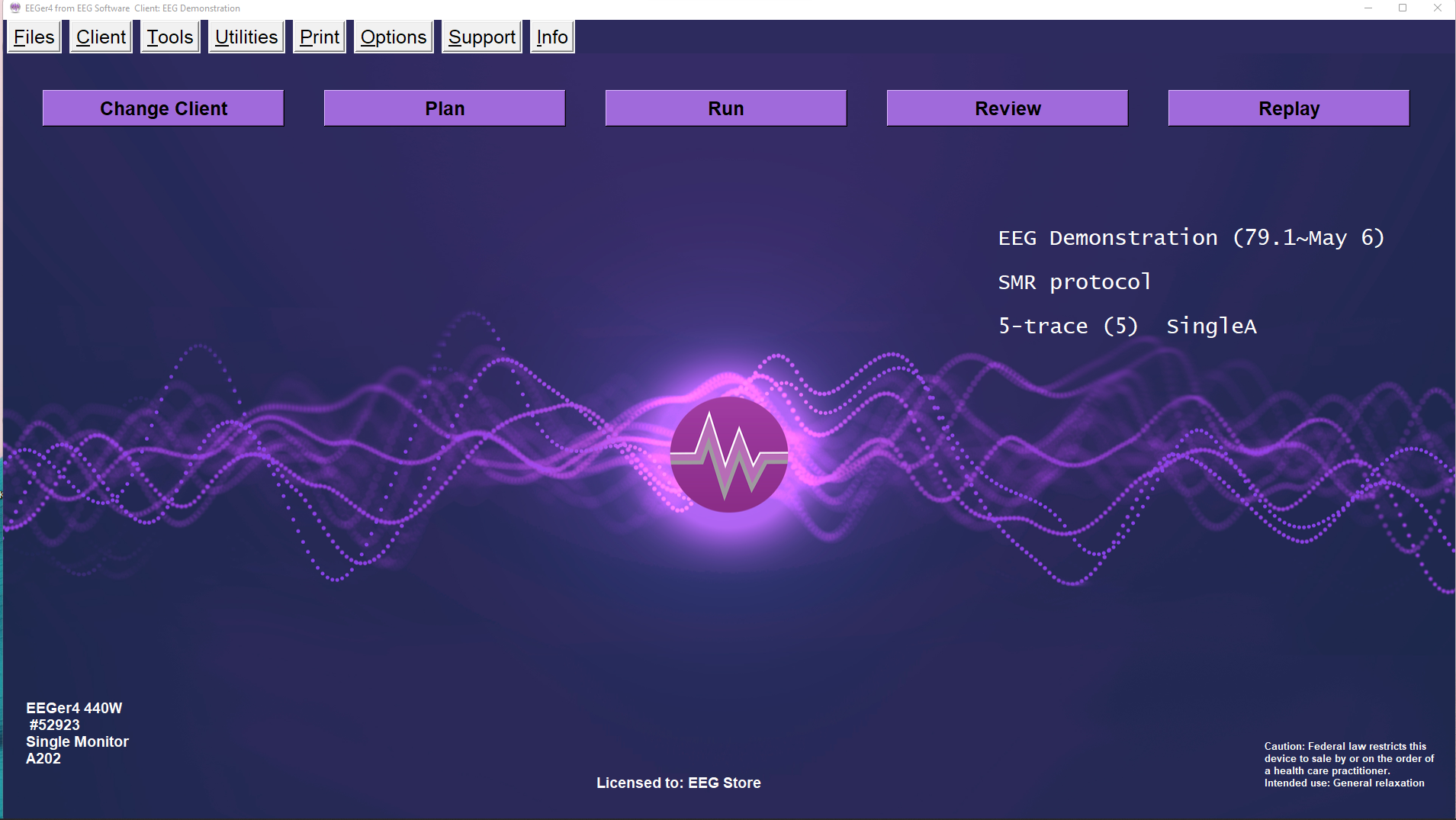
To begin a live session, click on the Runbutton on main EEGer screen. This brings up the game selection screen with a list of choices. Games shown in pink are NOT licensed and cannot be selected. Games with * cannot be selected in single monitor mode.
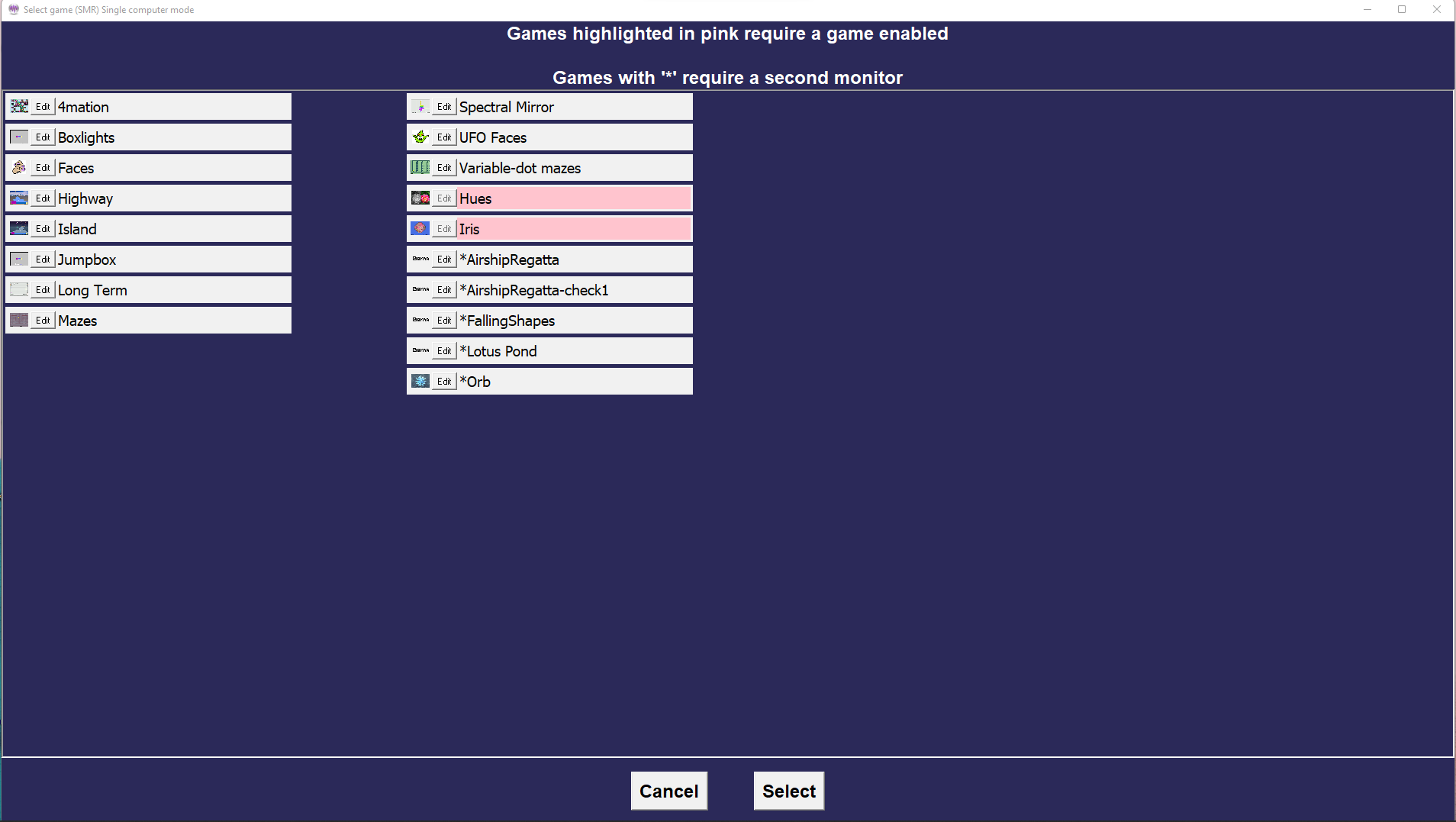
Clicking on the Edit button brings up a game tailoring screen. Changes made here affect ONLY this selection and are not saved as defaults.
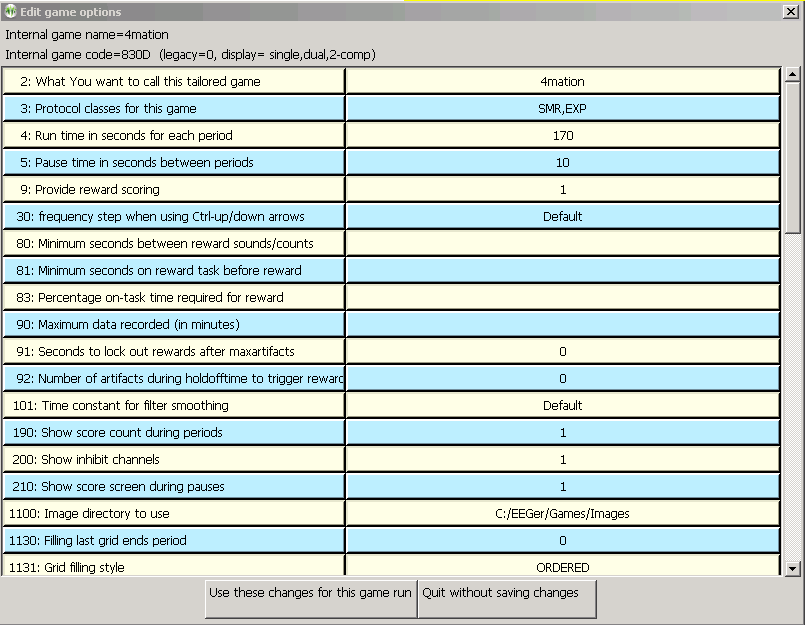
To configure/tailor a game to save it as a default or by other names, refer to Appendix 14: Game Tailoring Options
Selecting a game (highlight and click Select or double-click on game line) brings up the realtime display screens. Functions and operations on realtime session screen is described in Session Screens and Controls.
The Review Sessions button brings up the session review screens for post-session analysis. These screens and controls are described in Review .
Clicking on the Replay a Session button brings up a list of raw data files to choose to replay.
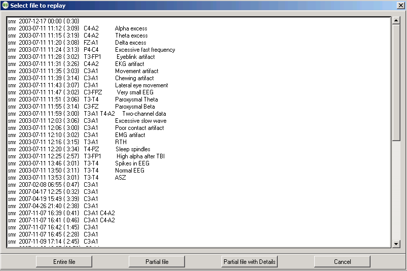
Clicking on Partial file brings up a selection option which allows just a portion of the file to be used.
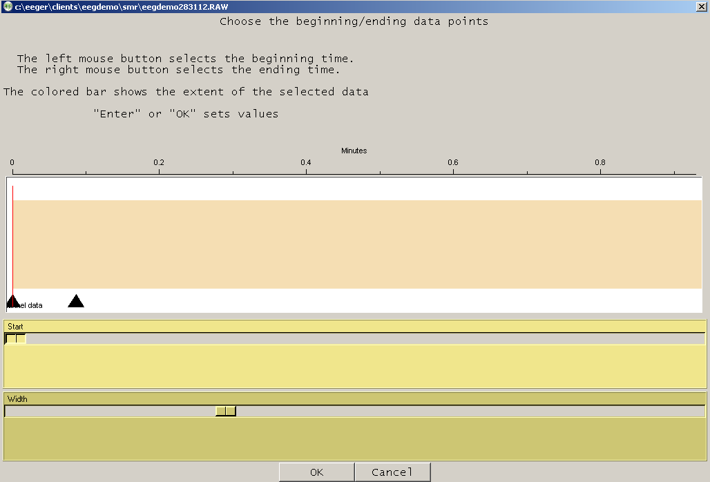
If you select the Partial file with Detailsoption, be prepared to wait for some time since the details include the actual waveshape of the data.
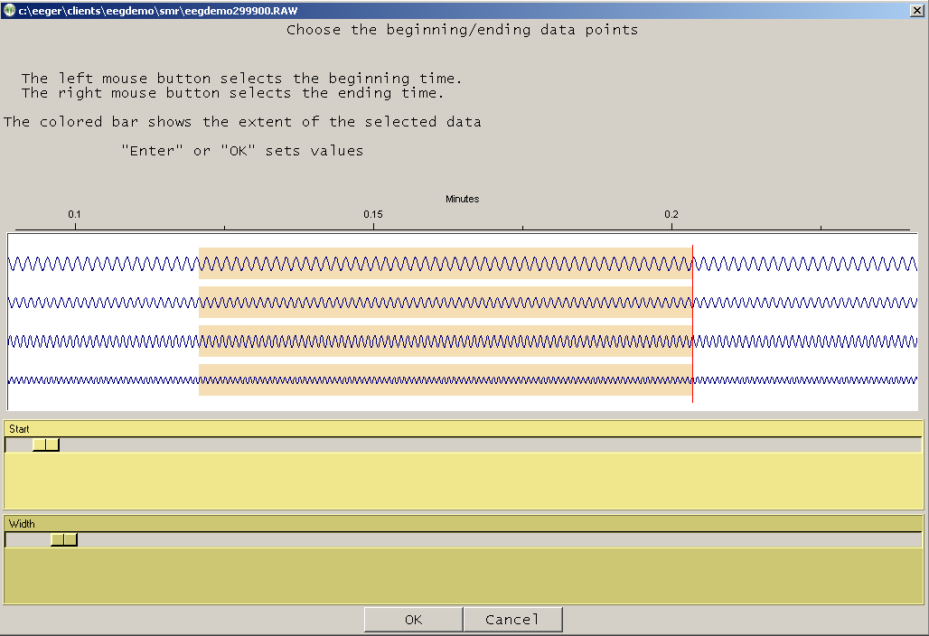
The top slider controls the origin of the left edge of the graph. The bottom slider controls the “time” width of the displayed data.
After selecting the replay file, a game must be chosen.
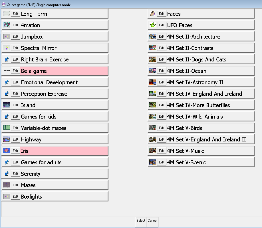
At this point, the feedback screens come up. During replay, new summary and data files are NOT stored, nor can Shift-F8 be used for annotation (since no new files are being saved). The F8 editor option DOESwork so you can add notes or comments while observing the replay of a past session.
The brainwave screen looks like this:
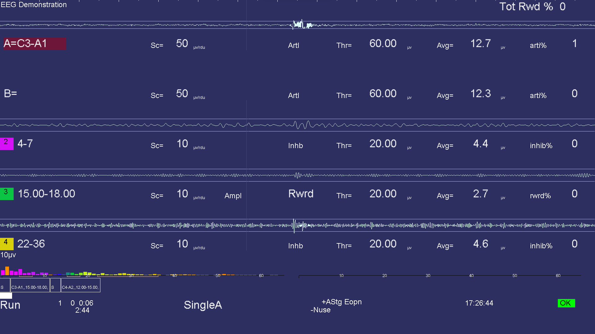
There is a lot of information on this screen. Generally speaking, the upper part of the screen contains signal data and the lower part contains process/progress data.
There are several popup menus which can be used to control autogoal thresholds, volume, tactile feedback settings, etc. The menus work alike in that the line to alter is controlled by PageUp/PageDown and the settings change by the "+" and "-" keys or left/right arrow keys (just like threshold settings).
The Esckey closes any popup screens and continues processing. If no popups and in Run/Rest, it places EEGer into Pausestate. If in Pausestate, it terminates realtime processing (without warning) and returns to the top menu.
This previous screen shows a typical single channel setup. The top two streams are the input channels (labeled “A” and “B”). The “A” channel electrodes are at C3-A1. The highlight of the channel/trace labels shows which input channels are being used for feedback. The type of feedback mode used during the session can be observed at the bottom (in the screen above SingleA is shown as the current feedback mode)
The three streams below that are reward and inhibit streams (labeled at about the middle of each stream display). Possible legends are:
ArtI Artifact Inhibit (lowpass data)
Inhb Inhibit
Rwrd Reward (signal above threshold
Down Reward (signal below threshold)
Monitor
(Additionally, for advanced users:)
Cntr Reward (signal close to threshold)
Elev Reward (signal above threshold, clamp to threshold)
DevU Reward (deviation above)
DevD Reward (deviation down)
Band Band
(within band limits of threshold setting)
The current frequency range of each stream is shown at the left near the colored blocks. The “color” of the blocks is based on the center frequency of the frequency range (using the customizable colors previously mentioned in the Tools menu description). The Sc (scale), Thr (threshold), and Avg (average) values are in microvolts/rdu or in absolute for non-voltage values like ratios, etc. The inhib% value is the percent of time the signal was over the threshold voltage (for inhibits). The rwrd% is the percentage of time in reward state (smoothed over the previous 30 seconds). The Avg value is the average value of the signal smoothed over the previous (user-specified) 30 seconds. The blue horizontal lines represent the relative position of the threshold setting. The Tot Rew % value in the upper right corner is the (smoothed over 30 seconds) percent of time the client is in overall reward state (no inhibits/artifacts and in rewardable state).
The (frequency) colored bars at the bottom are a measure of the energy contained in each 1 Hertz frequency range from 0 to 45 Hz. They are computed as FFT (Fast Fourier Transform) values every ½ second. If the FFT Highlight mode is on (toggled by Alt-F10), the highest/lowest FFT amplitudes between 1 and 20 Hz will be color-coded with colors 49/50 of the current color set. This is a method of seeing where dominant values lie every ½ second. The FFT scale maximum value is shown in microvolts on the left of the FFT area.
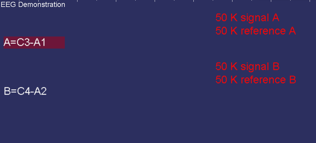
Some amplifier/encoders have a built-in impedance measurement
capability. If the device used has this capability, the Ctrl-F7
option while NOT running (Pause or Stage mode) turns this measurement mode
on or off. When on, the red letters shown below on the brainwave
screen report the kilohms of impedance detected.
The above example shows very large values for the B trace since no electrodes are connected to the B channel. You should ensure that the reported impedance signal and reference values for a channel are similar in range and generally below 10 K. During impedance mode, no trace data is shown.
If there are scratches (or mismatches) on the electrodes, a large dc value may be reported as shown below. Generally, this means the electrodes need to be replaced.
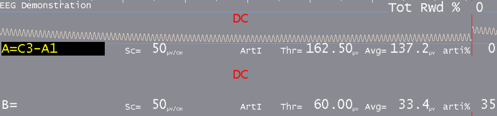
A typical two-channel screen is shown below. Several other features are shown on this screen. The reward stream shows a GREEN line in the center meaning signal-in-reward-condition. The high frequency band below it has a RED line meaning signal-above-threshold. Red lines inhibit rewards while green lines permit rewards (if there are no inhibits). The red lines in the input streams are times when an artifact (signal over threshold) has been detected/processed. The horizontal green lines are times when all reward criteria have been met (no artifacts/inhibits and all rewards OK). The vertical green lines reaching from threshold line to threshold line indicate a reward/“score” has been issued.
When Reward event Blob is enabled (EEGer configuration> preference), During a live session, users can observe a green reward blob being activated in rewardable state.
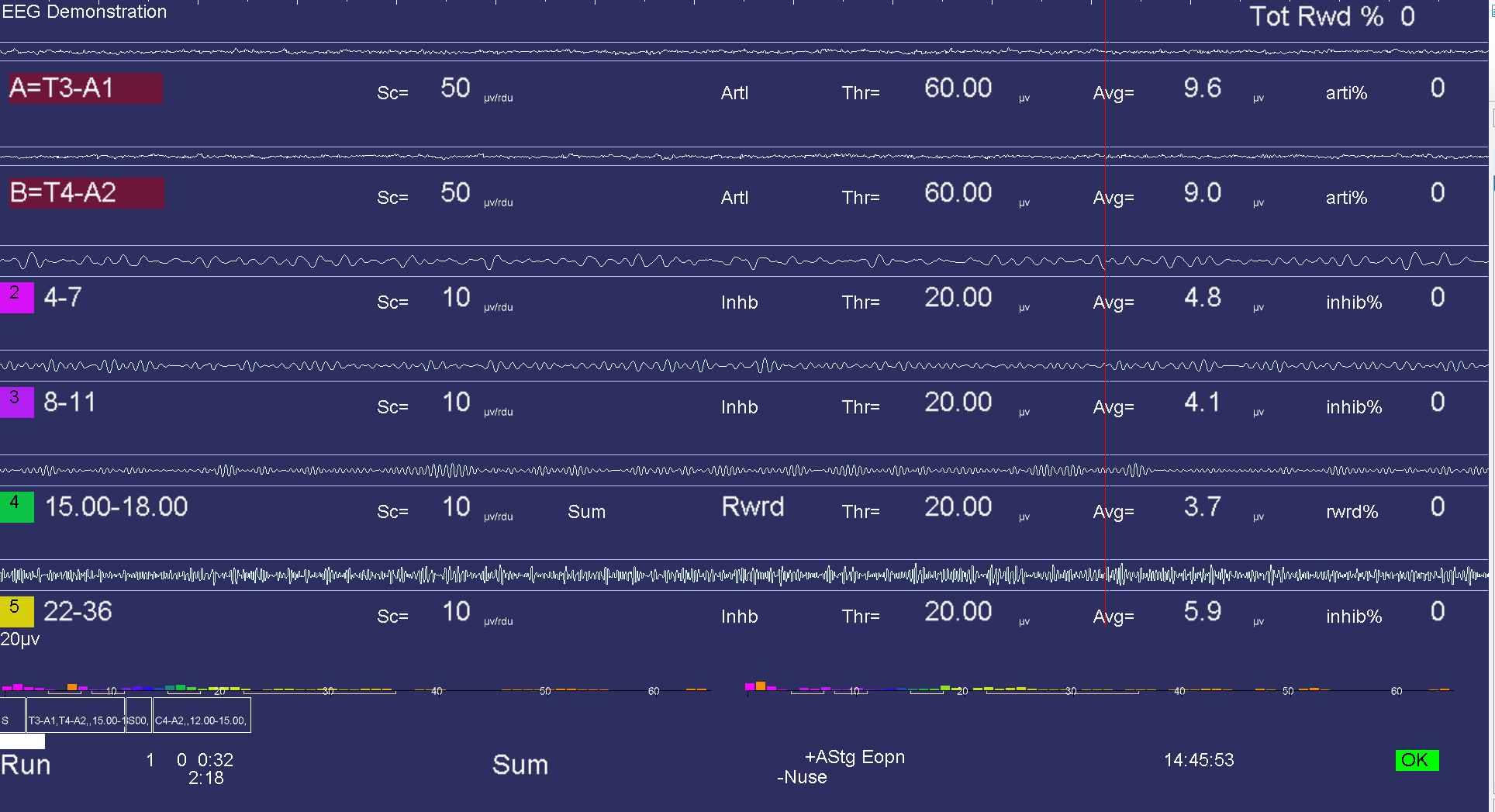
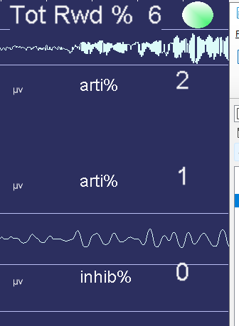
A 4-channel display has similar characteristics:
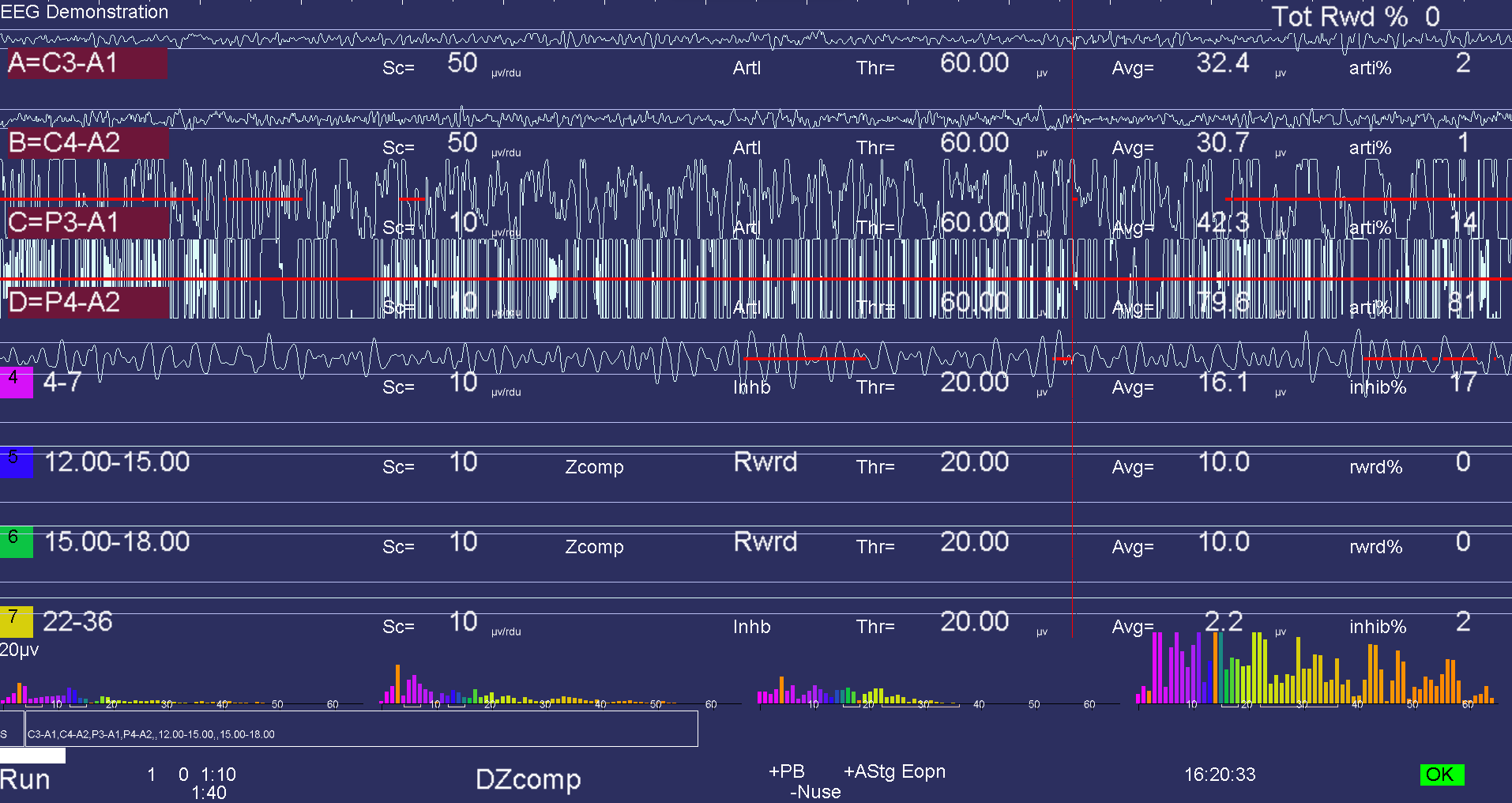
The bottom area of the realtime screen has a number of regions of data. Shown below are some boxes with text inside. This is a graphical representation of the session plan. The little boxes with “S” inside represent Setup stages. The run stages have the setup text from the previous setup and a width proportional to the specified run time. The entire bottom width is scaled to represent the maximum session time (from the preferences screen). The white progress bar is filled in to show the current position in the session plan.
Below the boxes is a line of status information. The leftmost field contains the current status of feedback (Pause, Run, Rest, Stage, Wait) with a different background color for each status. “Pause” is shown when an operator action (F5) is required to continue the session. “Rest” status is shown during the rest periods between periods and implies no operator action is required. “Stage” is shown when there is an operator action/decision needed (move electrodes, continue/change session process, etc.). “Wait” is shown while waiting for the game to respond to its initialization.
The current period, score, and feedback time (minutes:seconds) is shown to the right of the current status. Below the feedback time is shown the time remaining before a status change takes place (like Run to Rest or Rest to Run). Next is shown the current feedback mode (SingleA).
There are a number of flags and operator-changeable modes whose state is shown in the middle of this line. Possibilities are:
+PB playback mode (not live)
+Gen signal generator mode (not live)
+Athr autothreshold (auto F11) at beginning of rest period or at some user-specified rate
+Astg auto stage processing enabled
+Arpl Auto replay running
-DC DC compensation turned off
-Ainh artifact inhibit turned off
-lpf lowpass filter disabled
-Nuse unused raw trace data is suppressed
Eopn Eyes open
Ecls Eyes closed
+All Recording of multi-channel data is enabled
Further right the current time-of-day is shown.
The boxes, text, and bar disappear if the session plan is no longer being followed.
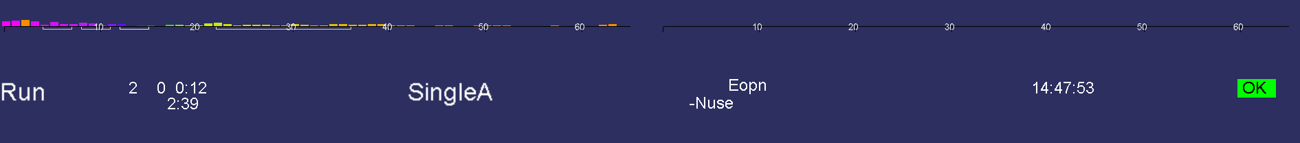
Additionally, some generic messages may be shown about the feedback process.
Among them are:
NOT RUNNING - EEGer paused before first run
REWARDS BLOCKED - No more rewards are sent to game. This is usually
caused by manually exiting a game during feedback.
NOT RECORDING - Session has run more than 90 minutes. Feedback can
continue but no more data recording will occur.
INPUT FAILURE - Live input lost (amplifier failure or dongle removed)
KEYBOARD Lost - EEGer is not the focus for keyboard inputs. If this occurs,
move the mouse to the brainwave screen and left-click.
RAW% TOO HIGH -One of the in-use raw channels has too many artifacts.
Please adjust artifact thresholds until percentage gets lower
and then readjust as needed.
TRACE NOT SELECTED -A trace was not highlighted to tell which trace is to be
used/modified.
If the keyboard focus is taken by another program (such as Boat Race or Grind),
this will appear:
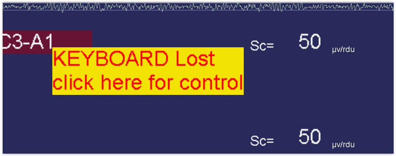
Clicking the mouse on the yellow block will return the keyboard to EEGer.
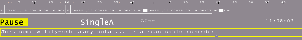
Pressing Shift-F8 causes the two bottom lines to be used as a single-line entry area as shown below. This data is recorded and displayed during review.
F8 raises/lowers the editor screen which can be used while feedback is ongoing.
There are a number of popup menus which can be used to control autogoal thresholds, volume, etc.,. The menus work alike in that the line to alter is controlled by PageUp/PageDown or the Up/Down arrow keys and the settings changed by the “+” and “-” keys or Left/Right arrow keys.
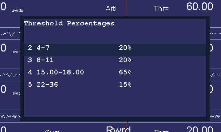
The autogoal threshold popup is initiated/dismissed by the “%” or
the “G” keys.
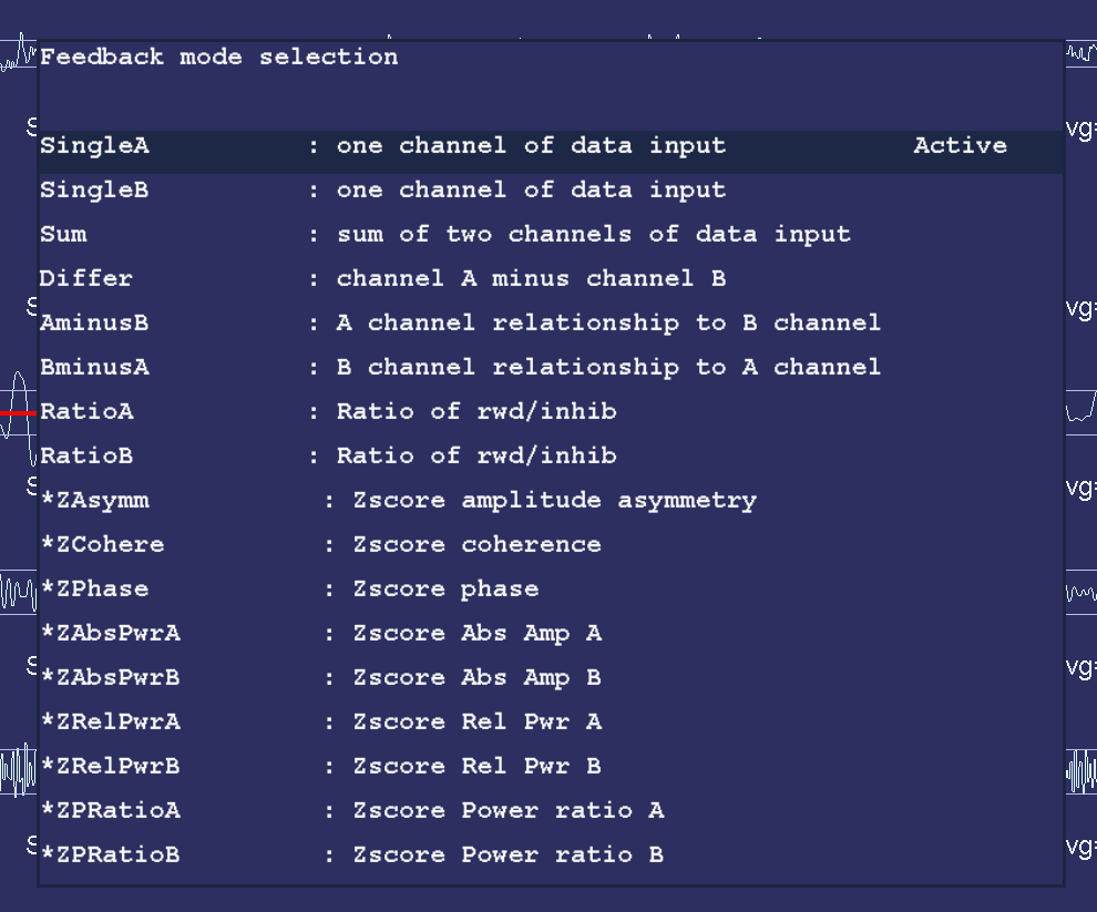
The Feedback Mode popup is selected/dismissed by the Shift-F3 key.
Only valid modes for the current layout are
shown. The first window shows the standard modes.
A second Shift-F3 brings up the advanced mode window.
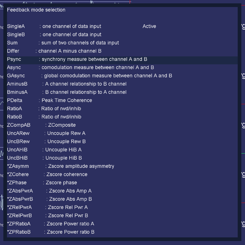
The volume popup is selected/dismissed by the “V” key. Volume controls here only work for those games which “understand”, in particular the EGS games.
For SMR and EXP protocol classes, the volume popup looks like this:
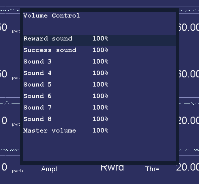
If an Alpha Theta session is being run, the volume popup looks like this:
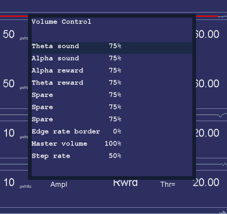
The tactile feedback popup is initiated/dismissed by the “T” key. This popup is only enabled if a tactile audio device was selected on the configuration menu.
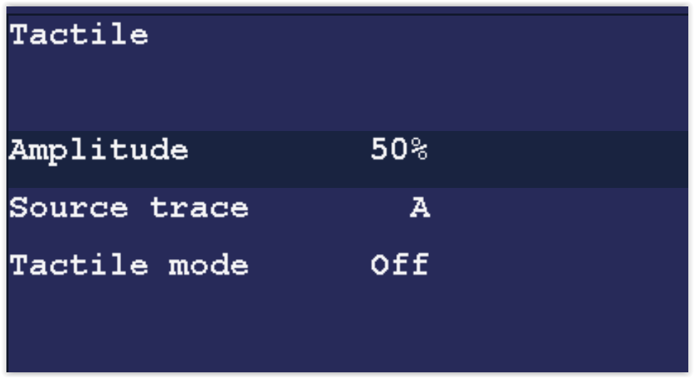
Any trace can be selected as the source of tactile data. The tactile mode can be OFF, 10 Hz, 60 Hz, or 160 Hz. This is the frequency of the signal being modulated by the source trace amplitude. Note that many laptops cannot produce 10 Hz signals due to poor audio systems.
The “P” key initiates/dismisses the peripheral data control.
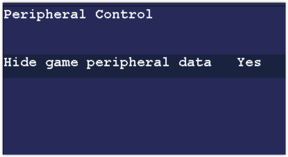
The “Hide game peripheral data” option controls display of peripheral data on the game long-term display (just as the control on the Game Feedback Control menu does).
Other options depend upon the peripheral types specified in the Device Options configuration page. In general, there will be an enable/disable option and minimum/maximum value options.
The “D” key initiates/dismisses the Therapist Display Control. This controls ONLY the Therapist display options.
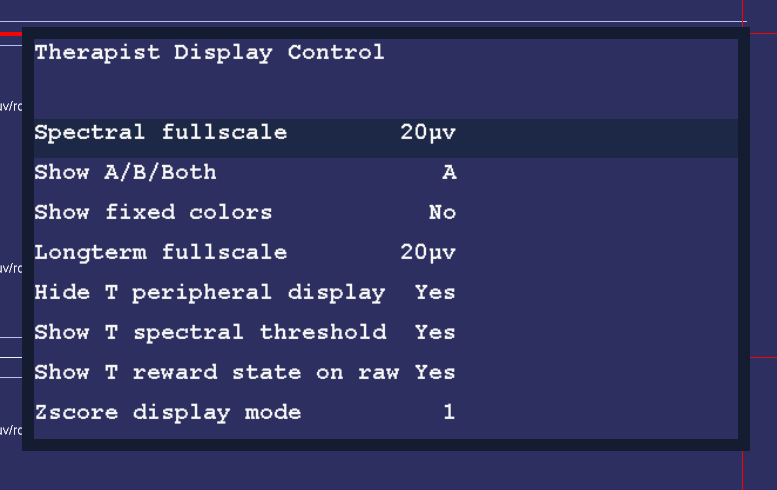
The “Spectral fullscale” setting controls the full-scale setting of the Therapist Spectral Mirror display.
The “Show A/B/Both” control determines if the Therapist sees just the A trace signal mirrored, just the B trace signal mirrored, or both (A on the left and B on the right). For 4-channel systems, C, D and C&D are also available.
The “Show fixed colors” option determines if the fixed color set is used instead of the user-chosen color set (but just on the Therapist displays).
The “Longterm fullscale” setting is another way to control the long-term display scale.
The “Hide T peripheral display” removes the peripheral data from the long-term display (assuming there is any peripheral data).
The "Show T spectral threshold" controls whether or not the threshold and average values are displayed over the spectral mirror display.
The "Show T reward state on raw" option controls display of the green reward line display on the raw traces.
The “Zscore display mode” option determines if the zdisplay bar colors are driven by the over/under logic.
The “F” key initiates/dismisses the “Game Feedback Display Control” popup. Note that this controls only display aspects at the client display and not any feedback decisions/controls.
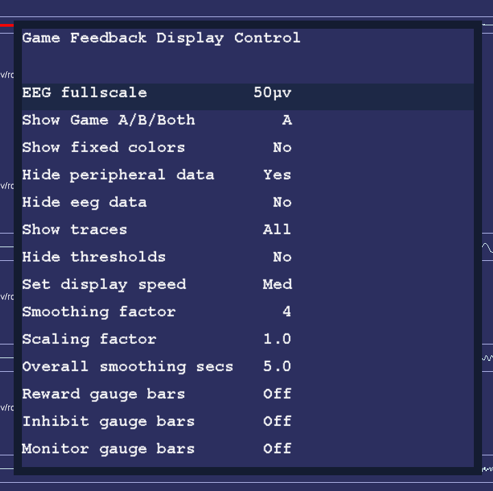
“EEG fullscale” controls the scale used on both the game long-term display and the game spectral mirror display.
The “Show A/B/Both” option controls whether the game spectral display shows A mirrored, B mirrored, or both A & B.
The “Show fixed colors” causes the game long-term display to use fixed colors rather than the color set selected in the game tailoring logic.
The “Hide peripheral data” option hides/shows the peripheral data (if there is any) on the game long-term display.
The “Hide EEG data” option controls display of the EEG data on the game long-term display.
The “Show traces” option allows selection of all traces, just the uppermost reward trace, or the uppermost reward and the inhibit just above the uppermost reward trace.
The “Hide thresholds” option controls display of the EEG threshold(s) for the selected trace(s).
The “Set display speed” allows selection of slow, medium, or fast displays of data. The slow display shows the entire session. The medium display shows ten minutes of data. The fast display shows one minute of data. The “per” display shows one period of data.
The “Smoothing factor” controls how smooth the data will be on the display (just as is done in the Review process).
The “Scaling factor” option changes the scaling logic for the IRIS game display.
The “Overall smoothing factor” allows changing the smoothing time constant for games that use overall reward as the driving factor.
This menu has different values depending on the currently running game and is initiated with the “S” key. One set of games uses this menu:
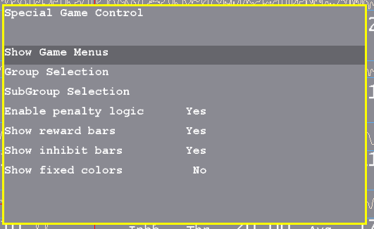
“Show Game Menus” allows hiding/showing of the special game selection menu. A '+' raises the screen and a '-' hides it. The menu is only displayed if EEGer is in a PAUSE or STAGE state. The special menu shows the title of the main group, the current subgroup, and the instructions for the client for the current game/subgame.
“Group Selection” cycles through all the allowed game main game groups.
“SubGroup Selection” cycles through the subgroups of the current game game group.
“Enable penalty logic” turns on/off the logic in the game that backs up displaying pieces if rewards do not occur within the timeout. This only works if the game definition has a time specified for the timeout.
“Show reward bars” turns on/off the display of the reward amplitude bars at the bottom of the game display. The threshold setting is the bottom of the picture and the reward bars are on the right side.
"Show inhibit bars" turns on/off the display of the inhibit amplitude bars at the bottom of the game display. The threshold setting is the bottom of the picture and the inhibit bars are on the left side.
"Show fixed colors" turns on/off the display of fixed colors (instead of the frequency sensitive colors) in the reward/inhibit bars.
The DVD game has this menu:
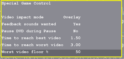
“Video impact mode“ allows selection of the video modification applied to the current video playback. Choices are Overlay, Blur, Black White.
“Feedback sounds wanted“ allows feedback sounds (reward, etc.) to be heard.
“Pause DVD during pause” allows pausing/not pausing video playback during PAUSE or STAGE phases.
“Time to reach best video” is the number of seconds of on-task time to reach minimal video modification.
“Time to reach worst video” is the decay time in seconds to reach the most video modification.
“Worst video floor %” is the minimum amount of video that will always be seen. Setting 100% means that NO video modification is performed. Setting 0 % means that the full range of modification/obscuration will be performed.
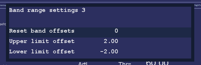
“Reset band offsets” sets the upper and lower offset limits to 10% of the current threshold setting.
“Upper limit offset” adjusts the allowable range above the threshold for a rewardable condition.
“Lower limit offset” adjusts the allowable range below the threshold for a rewardable condition.
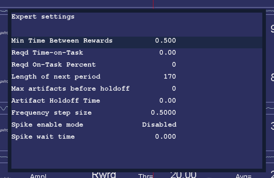
“Min Time between Rewards” allows changing the minimum time between rewards from the value set by the game definitions (down to a minimum of 0.25 seconds).
“Reqd Time-on-Task” allows setting the minimum seconds needed to be in a rewardable state before a reward is allowed.
“Reqd On-Task Percent” allows setting the minimum overall reward rate required before rewards are allowed.
"Length of next period" allows setting the length of the next feedback period in seconds.
“Max artifacts before holdoff” allows setting the number of artifacts within the holdoff time before rewards are inhibited for the holdoff time.
“Artifact holdoff time” allows setting the artifact monitoring period and the length of holdoff if the count is exceeded.
“Frequency step size” allows changing the step size used when changing the reward-band frequency when using the Ctrl-Up and Ctrl-Down arrows.
“Spike enable mode” allows changing the spike detector mode. Any mode except 'Disabled' causes (yellow) vertical bars to be shown on the raw traces. If mode is “In Period” or “Always”, an optional sound can e produced on the game computer. Modes are:
Disabled
In Period - display on therapist display, sound triggered on game if in feedback
Always - display on therapist display, sound triggered on game at any time
Just Show - display on therapist display
“Spike wait time” allows selection of how long to wait after a spike to see if its really an artifact.
Note that these changes are NOT saved for future sessions.
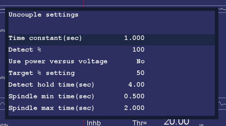
This popup allows changes to the uncouple settings. These settings ONLY affect the special uncouple feedback modes.
Time constant (sec) allows changing the time constant used for averaging the trace data being monitored. This is usually the inhibit channel just before the reward trace.
Detect % sets the amount of power/voltage OVER the average used to detect a spindle.
Use power versus voltage allows choosing power for the value being detected.
Target % setting allows change how the target trace threshold will be set during the hold time. The target trace is implicitly set by the uncouple feedback mode (usually either the reward trace itself or the inhibit trace immediately below the reward trace). This modification will only be made for the selected hold time and (color) highlighted during its change.
Detect hold time (sec) sets how many seconds long the target threshold modification is made.
Spindle min time (sec) sets the minimum width of a detected spindle.
Spindle max time (sec) sets the maximum width of a detected spindle.
Note that these changes are NOT saved for future sessions.
The F1 key brings up a several help displays that shows the key usage during feedback. When pressed with help not already displayed, it brings up the primary help display.
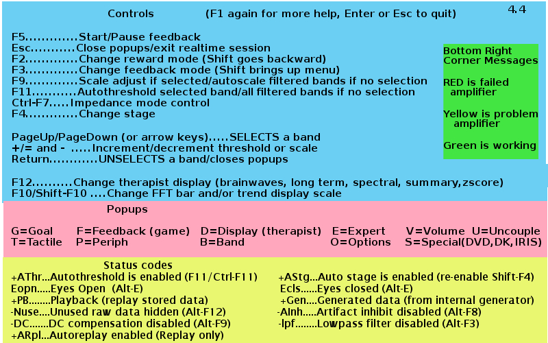
Pressing F1 again brings up this display:
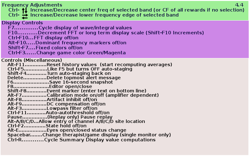
Another press of F1 removes the help display and returns to the previous display.
If there is some problem with (lack of) graphics memory or if Shift-F1 is pressed, the following textual display may appear (containing the same information).
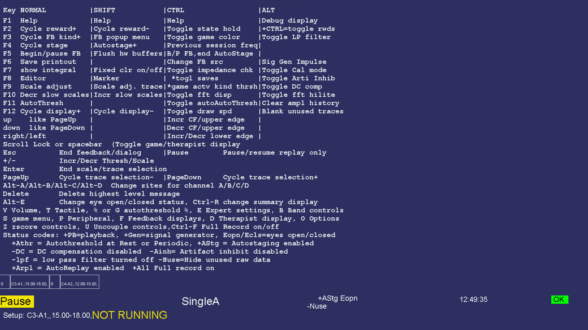
The debug screen contains (cryptic) information for use in troubleshooting and further development of EEGer. It is selected/terminated by the Alt-F1 key.

Table of keys:
|
Key |
Modifier |
Action |
|
F1 |
|
Toggles help screen off/on |
|
|
Alt |
Toggles debug screen on/off |
|
|
Shift |
Toggles text mode help screen on/off |
|
F2 |
|
Cycle reward style to next available reward style Rwrd Reward (signal above threshold) Down Reward (signal below threshold) Cntr Reward (signal close to threshold) Elev Reward (signal above threshold, clamp to threshold) DevU Reward (deviation above) DevD Reward (deviation down) Band Reward (signal between limits) Note that switching between up and down rewards alters the target percentages. |
|
|
Shift |
Cycle reward style to previous available reward style |
|
|
Ctrl |
Toggle state-hold-required logic which inhibits rewards unless a state is maintained for the specified rate/time. |
|
F3 |
|
Cycle feedback mode to next available mode |
|
|
Shift |
Raise popup menu of available feedback modes |
|
|
Ctrl |
Toggle game 'color' between Green, Blue |
|
|
Alt |
Toggle lowpass filter on/off |
|
F4 |
|
Cycle to next stage; turns off autostage logic |
|
|
Shift |
*Turn autostaging back ON |
|
|
Ctrl |
Set frequency values to ending values from last run. |
|
F5 |
|
Begin/pause feedback |
|
|
Ctrl |
Begin/pause feedback; turn autostaging OFF |
|
|
|
|
|
F6 |
|
Save 16 second data sample for later printout |
|
|
Ctrl |
*Change feedback data source: raw, playback, signal generator |
|
|
Alt |
Signal generator impulse (if signal generator is source) |
|
F7 |
|
Show integral value instead of signal value on display (3 settings: just waveshape, just integral, both) |
|
|
Shift |
Toggle fixed colors on/off |
|
|
Ctrl |
Toggle impedance mode (if hardware-supported and in Pause) |
|
|
Alt |
Toggle calibration mode (if hardware supported) |
|
F8 |
|
Start/terminate editor |
|
|
Shift |
Insert marker. User has (60 second) option of entering a line of text. |
|
|
Ctrl |
*toggle saving debug data |
|
|
Alt |
Toggle artifact inhibit control on/off |
|
F9 |
|
Scale adjust. If no streams are selected (highlighted), performs autoscale of all non-lowpass streams. If a stream is selected, toggles between threshold and scale adjustment (using +/-). |
|
|
Shift |
Autoscales currently selected stream (including raw streams!) |
|
|
Ctrl |
* toggle game data activity control |
|
|
Alt |
Toggle DC compensation on/off |
|
F10 |
|
Decrease scale used to display FFT data and long term data |
|
|
Shift |
Increase scale used to display FFT data and long term data |
|
|
Ctrl |
Toggle FFT display on/off |
|
|
Alt |
Toggle FFT highlight mode |
|
F11 |
|
Autothreshold. If a stream is selected, choose appropriate threshold value for only that stream. If the stream is a lowpass stream, choose threshold based on 1% over threshold as target. If no streams are selected, choose appropriate threshold value for all non-lowpass streams. If the user-specified threshold percentage is zero, no autothreshold action is ever taken on that stream. |
|
|
Ctrl |
Toggle automatic autothreshold at beginning of each reset period (or specified time frame) on/off. |
|
|
Alt |
Reset history data (used for display, autogoal, averages) |
|
F12 |
|
Cycle display shown. Current displays are: brainwave, long-term, spectral mirror, zscore, realtime summary |
|
|
Shift |
Cycle display shown in reverse order |
|
|
Ctrl |
Toggle drawing speed of brainwave screen between fast and slow (normal). |
|
|
Alt |
Toggle “hide unused traces” mode. Turns off DISPLAY of unused input/FFT traces to minimize screen confusion. |
|
Up arrow |
|
Just like Page Up |
|
|
Ctrl |
Increase reward center frequency or inhibit upper edge of selected stream. If no trace is selected, adjust ALL reward streams at the same time. |
|
Down arrow |
|
Just like Page Down |
|
|
Ctrl |
Decrease reward center frequency or inhibit upper edge of selected stream. If no trace is selected, adjust ALL reward streams at the same time. |
|
Right arrow |
Ctrl |
Increase frequency of reward lower edge (decreasing width) or inhibit lower edge of selected trace. |
|
Left arrow |
Ctrl |
Decrease frequency of reward lower edge (increasing width) or inhibit lower edge of selected trace. |
|
Spacebar |
(any) |
Toggle between Therapist display and game display if NOT entering text for an F8 mark |
|
Scroll Lock |
(any) |
Toggle between Therapist display and game display |
|
Pause |
(any) |
PLAYBACK ONLY. Pause/resume playback |
|
Esc |
(any) |
Exit popup screen if shown (goal/threshold, tactile, volume, help, debug). If not in Pause state, set Pause state. Otherwise, exit realtime processing and return to top menu |
|
+ or = |
|
Increase threshold/scale value on selected stream. |
|
|
Shift |
Increase threshold/scale value on selected stream by ½ step |
|
- |
|
Decrease threshold/scale value on selected stream. |
|
|
Shift |
Decrease threshold/scale value on selected stream by ½ step |
|
Enter |
(any) |
End scale/threshold selection. If a scale value is currently highlighted, Enter just switches to threshold modification mode. If a threshhold is highlighted, deselects trace. |
|
Page Up |
(any) |
Cycle trace selection upwards |
|
Page Down |
(any) |
Cycle trace selection downwards |
|
A |
Alt |
Start/terminate option to change the text for the site that the A channel is connected to. Automatically terminates (without change) after 60 seconds. |
|
B |
|
Popup/remove the Band Control popup (to adjust band reward mode range). |
|
|
Alt |
Start/terminate option to change the text for the site that the B channel is connected to. Automatically terminates (without change) after 60 seconds. |
|
C |
|
Continue feedback from a Rest state |
|
|
Alt |
Start/terminate option to change the text for the site that the C channel is connected to. Automatically terminates (without change) after 60 seconds. |
|
D |
|
Popup/remove Therapist Display Control menu |
|
|
Alt |
Start/terminate option to change the text for the site that the D channel is connected to. Automatically terminates (without change) after 60 seconds. |
|
P |
|
Popup/remove Peripheral Control menu |
|
|
Alt |
*Capture a screen dump of the current screen |
|
Delete |
(any) |
Delete highest priority message from display |
|
% or G |
|
Popup/remove target threshold setting menu |
|
V |
|
Popup/remove volume setting menu |
|
T |
|
Popup/remove tactile feedback controls |
|
S |
|
Popup/remove special game control menu (only for games that have game control menus) |
|
F |
|
Popup/remove Game Feedback Display menu |
|
|
Ctrl |
Turn on/off recording of multi-channel data (if enabled) |
|
E |
|
Popup/remove Expert settings menu |
|
|
Alt |
Change eyes open/closed status |
|
R |
Ctrl |
Change the Summary display values WHILE IN STAGE/PAUSE MODE from end-of-period to various recomputed values. |
|
U |
|
Popup/remove uncouple settings menu |
Items in the table marked with an asterisk (*) are provided as debug aids only.
The long-term display (selected with F12) shown below is a display of signal amplitudes drawn at a one-second interval during the session. The width of the display is taken from the (user-preference-specified) maximum session time. The vertical scale of the display is set using F10/Shift-F10 or the Therapist Display Control popup menu. The (faint) vertical green lines mark beginning/ending of periods.
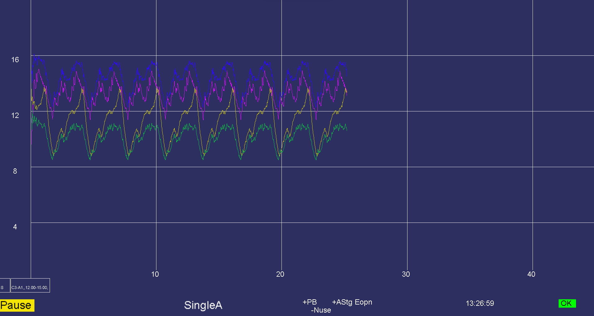
If peripheral data is displayed, it overlays the screen with its own scale.
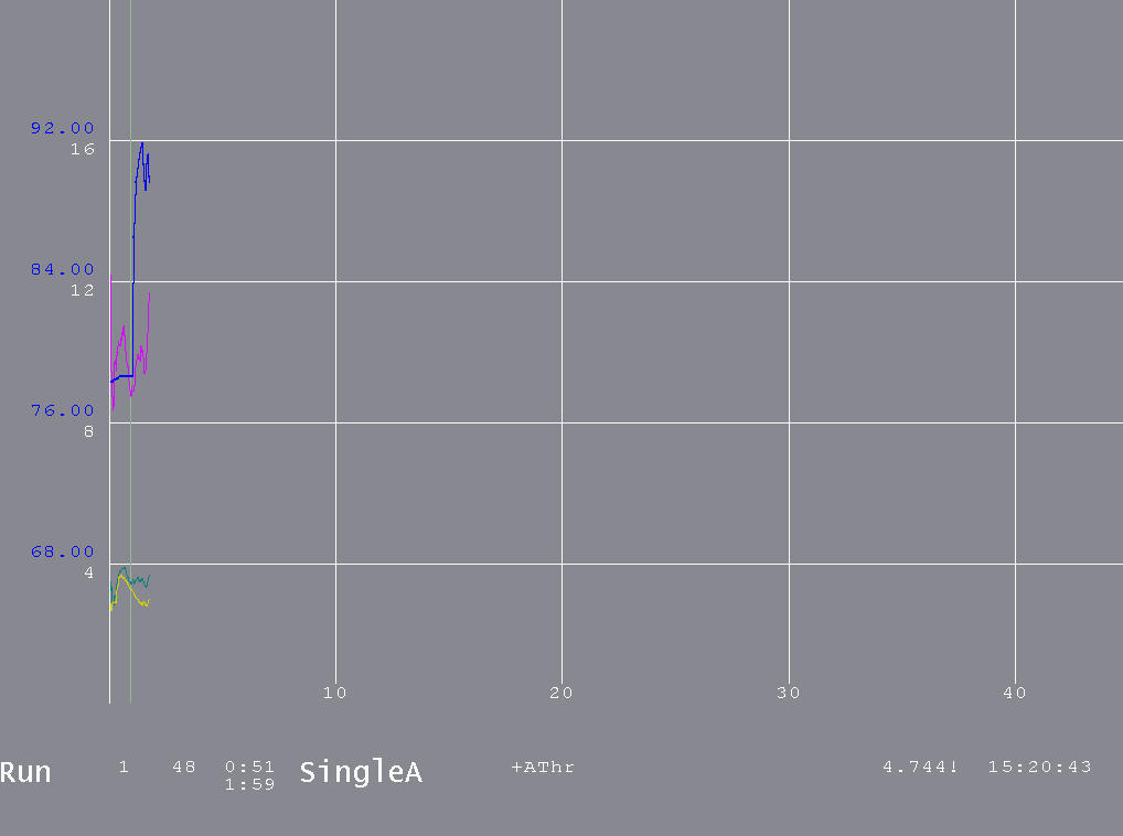
The Spectral Mirror display shown below displays the same spectral data as the FFT bars but in a different format. The “D” Therapist Display Control popup allows control over the scale for this display. The A channel is on the left and B channel on the right when A&B is selected as the display mode. For 4-channel modes, C&D can be selected where C is on the left (and either C or D can be also selected). Otherwise, a single channel is mirrored on left and right.
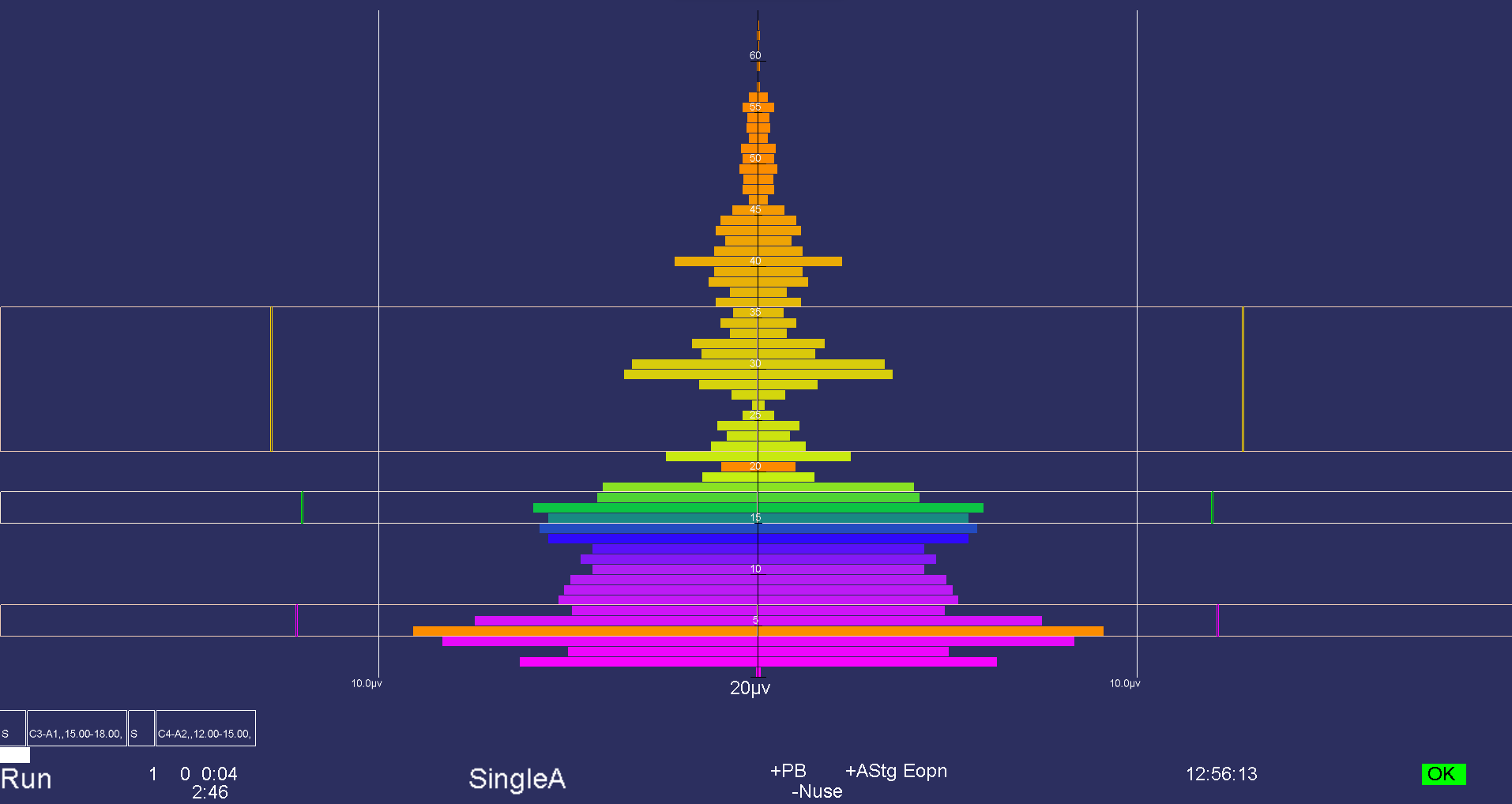
Notice that the filter bands are shown with a threshold value as the edge of the outline and the current average amplitude is shown as a vertical colored bar at the appropriate position. The orange bars are the dominant frequency markers.
The zscore display is only available if the ANI zscore module is installed and operating. Based on user selections during session planning or by realtime selections (shown below), the display shows various values in one of three colors and with two intensities. The display is organized by type of computation and by frequency band. Shown below is a 2-channel representation. Note: the displays are not of real data! The dim colors are values NOT being used for feedback while the bright colors are part of the reward/feedback decisions. A green color means the value is below the user-set “good” threshold, red means above the “bad” threshold, and yellow means between the two. Also, there are TWO displays of each value. The left-hand display of each value-pair is a 30-second moving average of the value while the right-hand value-pair is the 0.5 second moving average. These times are part of the time configuration setup.
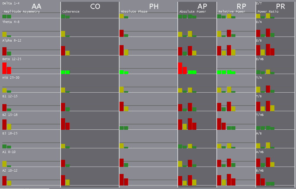
The conditions for reward/feedback can be set
during realtime using the Z popup display as shown
below.
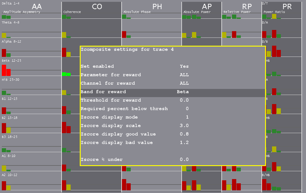
When operating in a 4-channel mode, there is much more data to display as represented below:
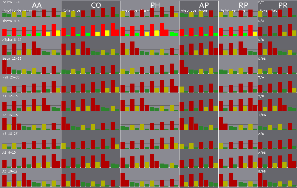
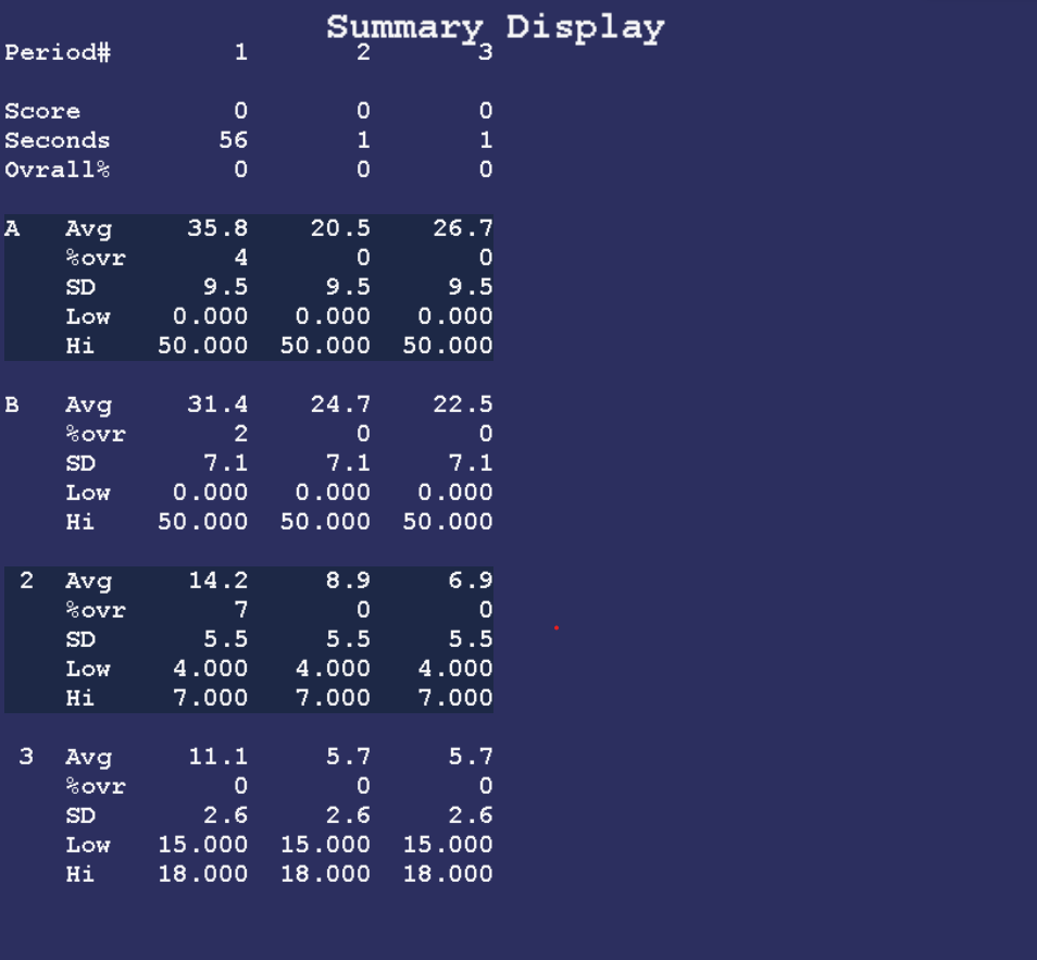
The realtime summary display shows significant
values for the latest 16 periods.
During a period, the (latest) current values are shown/updated. The end-of-period values are the same as those shown on the review data screens. Optionally, Ctrl-R can change to values to recomputed averages over the entire period or zero-suppressed averages over the whole period.
Of course, there will be more data than can be shown on one screen. PageUp/PageDown control display of additional trace data.
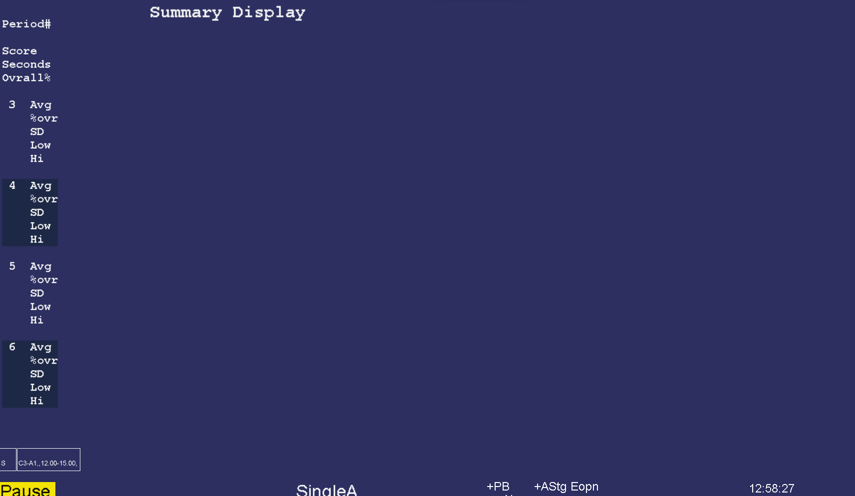
The Esc key closes any popup screens and continues processing. If no popups, it sets Pause mode. If Pause mode is set, it terminates realtime processing and returns to the top menu.
The Review button brings up the session review screens for post-session analysis. Most of the option selections are “sticky” - that is, they persist across all clients and review sessions until changed. A typical screen is shown. The top portion has a number of different display formats (graph, summary, bar, details, etc.). Shown is the Graph format with a single session's data shown in graphical format.
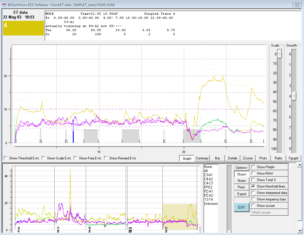
To the right of the graph are two sliders for controlling the scale and smoothing of the graphical data. Just below the graph are some checkboxes and buttons controlling the display at the top of this screen.
The graph shows each stream plotted as amplitude versus time (in minutes). The colors are the frequency-specific colors used throughout EEGer unless changed by a user option (discussed below). The short vertical black lines mark the beginning/ending of periods. Non-feedback times (paused or resting) are shown by the gray shading between period lines. Short red lines mark the time-location of significant events such as frequency changes, user F8 marks, etc.
Threshold change events, scale change events, and reward events can optionally be shown if the respective checkboxes are checked. These checkboxes also control whether threshold/scale changes appear in the details data. Whenever the mouse cursor is moved over the top graph area, the text display at the top represents the state at that (horizontal) time.
The top scale slider allows selection of a voltage scale for the session graph (or 0 for autoscaling). The smoothing slider allows control of data smoothing for graphical display. The value 4 represents 16-second smoothing and the value 5 represents 32-second smoothing. The value 0 is no smoothing.
The bottom graph is a trend graph of sessions. The colors of the lines are the frequency-specific colors used throughout EEGer. To the right of the trend graph is a list of all the sites used in the displayed sessions. To the right of that list is a scale slider allowing selection of a voltage scale for the trend graph (or 0 for autoscaling). At the right edge are some buttons and checkboxes allowing various options.
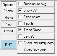
The options available are shown here: The
Show choices available are:
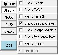
If there is zscore data embedded in the data file, the additional button choices for display after clicking on Which zscore are:
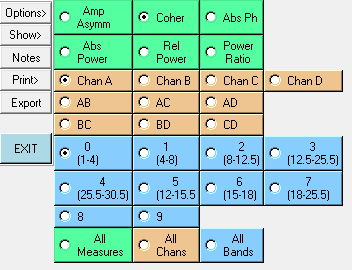
The Notes button brings up the embedded editor with notes for the current client. F8 can also be used to start/end the editor function. The Print button options will be either print direct or save options.
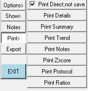
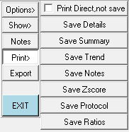
or
By default, the raw data streams are not shown. Clicking on the Show Raw checkbox toggles display of the raw data streams.
In some cases, it is hard to see/print the colors or to determine which stream is which if the frequencies (colors) are similar. The Fixed colors checkbox toggles between frequency-specific colors and a fixed set of colors that is independent of frequency.
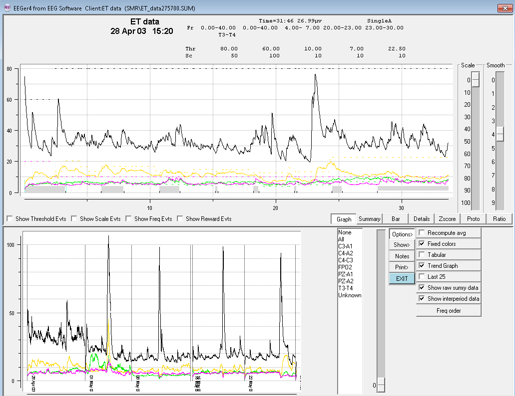
The screen below shows the summary data (text) for the currently-selected session. Clicking on one of the sites listed in the site list produces a gray shading (in the trend graph)for the periods where the selected site was used.
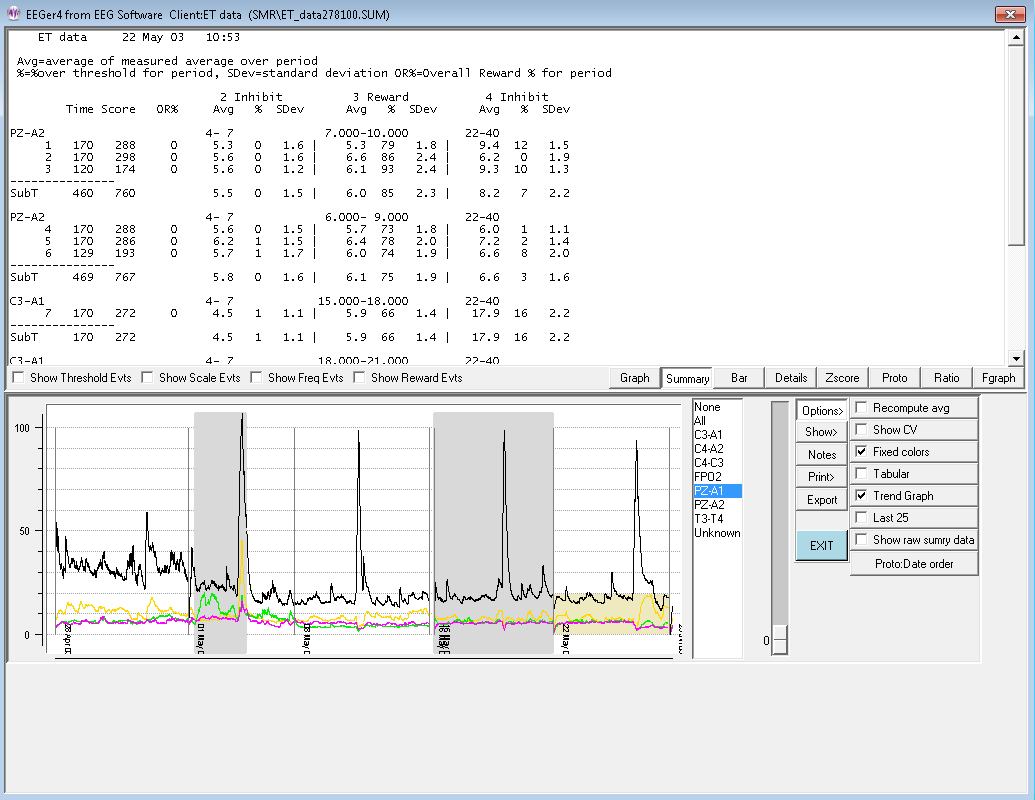
The average values shown above are the average values at the end of the period. Checking the “Recompute avg” checkbox produces the same display except that the average values are recomputed to be the average value across the entire period rather than just the ending values.
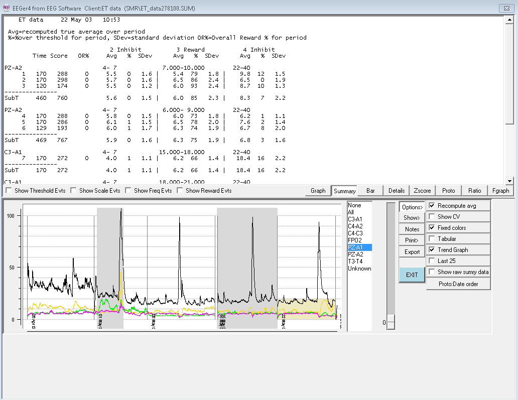
Below is the same screen with the interperiod data shown. The interperiod data is the average value and standard deviation of the time BETWEEN feedback periods. Note that some of that cannot be seen on the screen until scrolled down. All the data will be printed or saved at one time.
There is also an option to display the Coefficent of Variation (CV) for the summary data. This value is computed and displayed as a percentage (CV * 100).
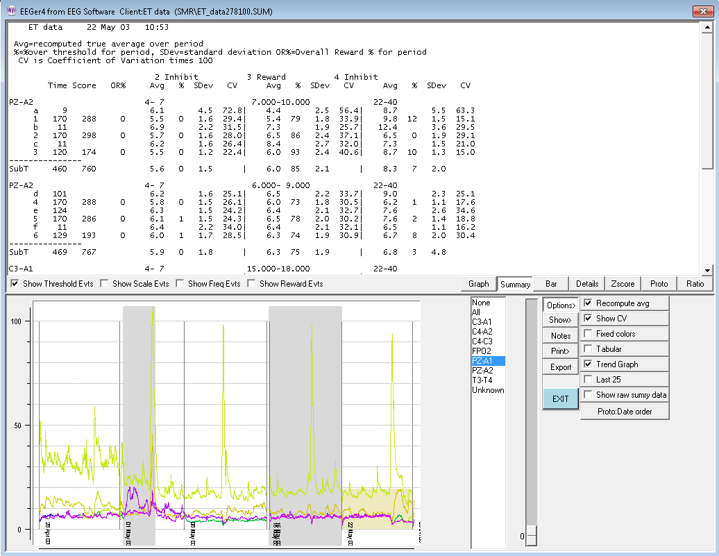
The Bar screen shows a barchart representation of the time (red bars) and scores (frequency specific color at end of period) for the selected session's periods.
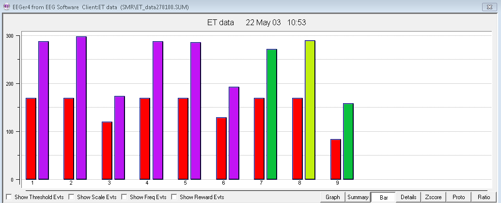
The following image shows the Details screen. This is a chronological list of significant events during the selected session.
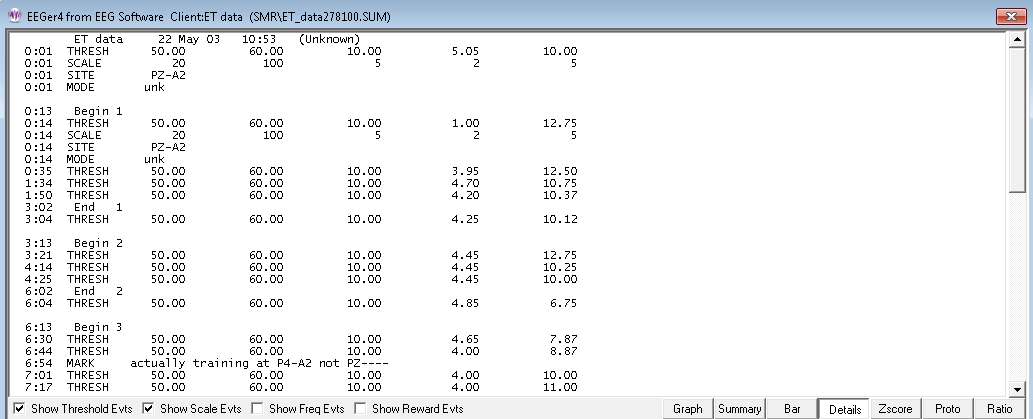
Note that the threshold and scale checkboxes were selected so that threshold and scale adjustments were reported. The time of the threshold/scale adjustment is the time at the beginning of the adjustment and the value at the end of the adjustment (10 seconds without change).
For recently acquired sessions, the details screen also displays the amplifier type used, the software version used, the game used, and the layout used for the session.
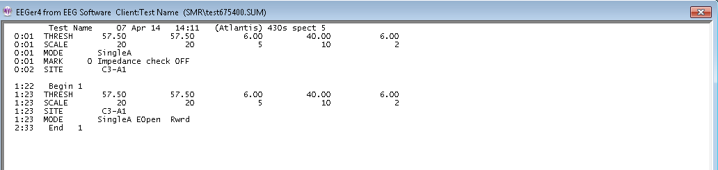
If there are many sessions, the Tabular checkbox allows display of all the sessions for the current client. Double-clicking on a line causes that session to be displayed in the top area.
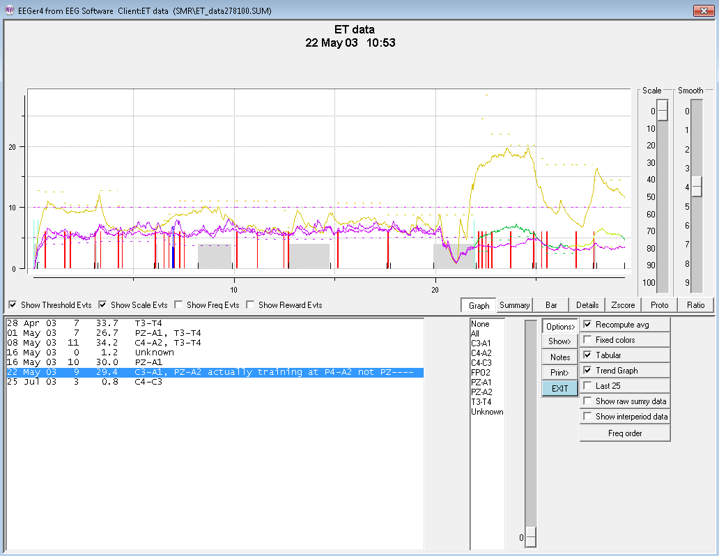
The Trend checkbutton controls whether or not the trend graph is shown on the bottom graph.
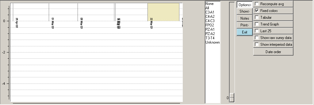
If the TOTAL % checkbox is selected, the total reward percentage will be shown on the graph as a bold green line.
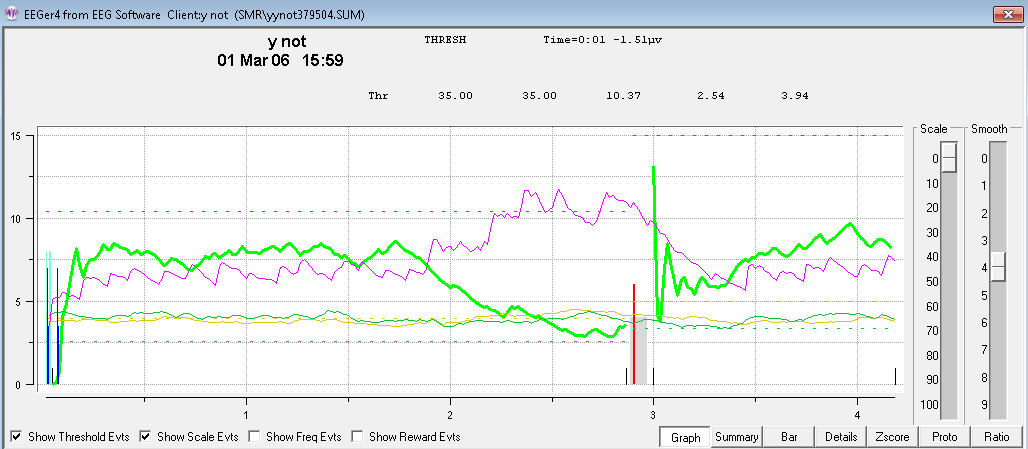
If peripheral data exists in the summary file, the Show Periph button controls the display of the data. The scale and graph line are drawn in a forest green color.
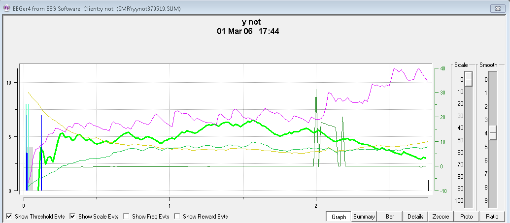
The zscore button shows one or more measures as selected by the “which zscore” buttons. The green buttons determine which zscore measures are selected. The blue buttons determine which frequency bands are selected. The beige buttons determine which channel or channels of data are selected.
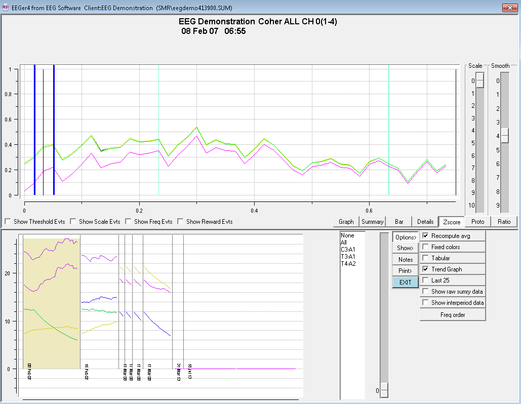
The displayed measure is always shown in the title of the graph, however, when too many multiple options are selected, only the last in sequence of values may be the “title”. Above is shown zscore coherence in the 1-4 Hz band.
Below is shown all measures in the 4-8 Hz band.
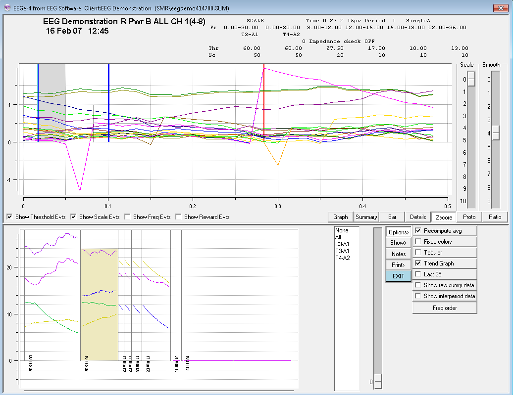
Below is a single zscore measure (coherence) for all bands using channels A and B as input.
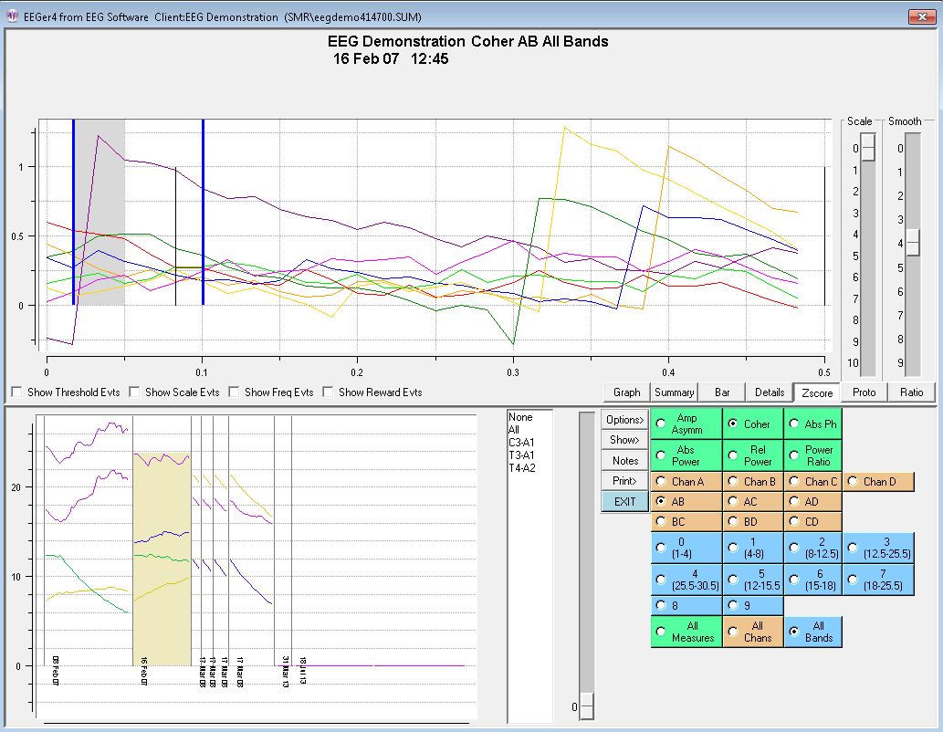
For completeness, you can also show all measures for all bands. It is pretty to look at but not of much use.
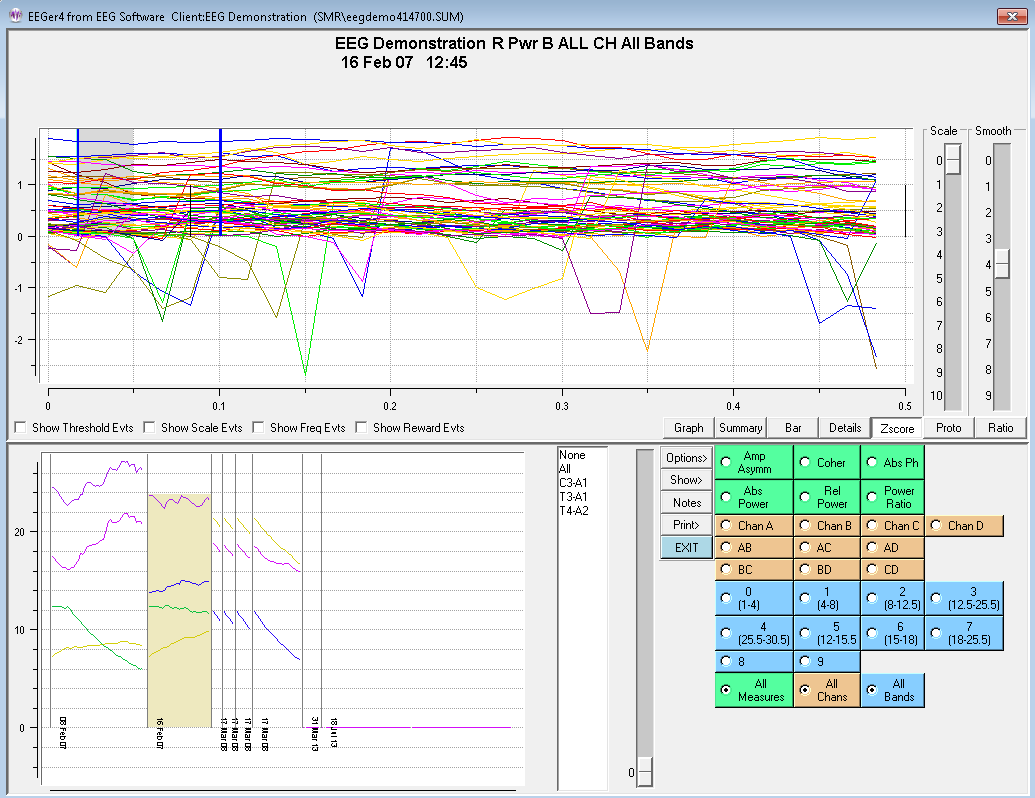
The Proto screen shows the (textual) values of the selected sessions (all or last 25) for the current client. This data is sorted by session date (Date order), frequency settings (Freq order), or reward frequency (Reward Freq order) as selected by the Option selection. Each group is comprised of like layouts, sites, feedback modes, and eyes open/closed status. Each line has the date of the session, the length (in minutes), and the frequency range/ending value/percent change for each band. The percent value will be 0 or 100 if the beginning value was zero (based on the ending value).
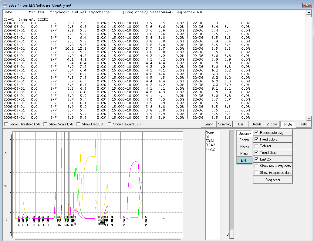
Order selection options are:
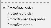
The Ratio selection computes various ratios between certain frequency bands. This data is recomputed from the raw data samples of the session so that the frequency bands need not match those used for feedback, inhibit, etc.
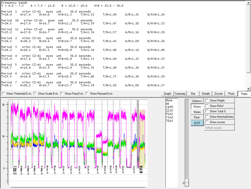
The top part of the window shows the frequencies associated with the letter legends (like T).
Below is a listing, by period, of the (moving-average) amplitudes (at the end of the period) for each frequency band and various ratios of those amplitudes.
The values shown are the default values. Using the Options method of Change review ratio frequencies/ratios, a user can select any combinations to output.
The Fgraph option shows the average voltage in each frequency during the selected period. The frequency width of the display can be selected as well as the artifacted state (no data during artifacts) of the computations.
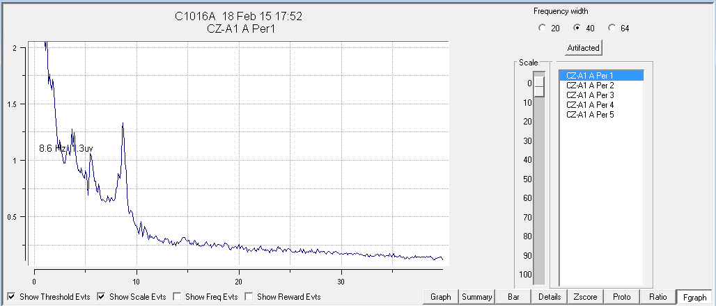
The Save Summary Printbutton causes two files to be created with the graph display in one and the summary data in the second for later printing (using the Print menu option). If the button says Print Summary, the two printouts will be directed immediately to the default Windows printer as two pages. If the option for a single page is select in the Preferences configuration menu, both printouts will be combined into a single file/printout page.Selection of the button actions is made in the Configuration->Preferences tab
The Save Details Print button causes a file to be created with the currently-selected options (threshold, scale actions) for later printing. If the button says Print Details, the printout will be directed immediately to the default Windows printer.
The Save Trend Print button causes a file to be created with the trend graph display. If the button says Print Trend, the trend graph will be directed immediately to the default Windows printer.
The Save Protocolprint button causes a file to be created with the protocol summary data (as currently ordered). If the button says Print Protocol, the printout will be directed immediately to the default Windows printer. Please note that the line wrapping can make the output hard to interpret. It may be better to use the Save Protocolmode and view the print file stored in the Print folder in some external program.
The Save Ratio Print button causes a (text) file to be created with the ratio values. If the button says Print Ratio, the ratio values will be directed immediately to the default Windows printer.
The Export button allows creation of a zip file containing selected session data. Clicking on the Export button brings up a screen similar to this:

This screen allows selection of zero or sessions to be exported. A trend report/graph is always exported. Only the sessions highlighted in red have reports exported. Clicking on the Quit button brings up an informational message:
If the OK button is selected, the review process creates a trend output followed by output of the top graphs and the summary data text files to the created zip file. When completed, the following message is displayed:
The file is created in the Exports folder and named after the
client codename along with a Z and the date. For example, here is
the contents of the ET_dataZ2014-03-20.zip file:
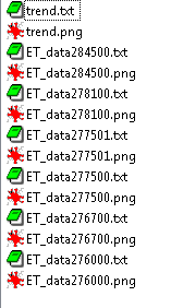
The Exit button returns to the top menu.
The EEGer Game Suite (EGS) comprises a set of feedback and display programs which support the Therapist software. The same games are used on single-computer systems and two-computer systems.
The feedback programs are comprised of ten displays:
Boxlights
Highway
Island
Fixed-dot mazes
Variable-dot mazes
Jumpbox
Theta-down highway
4mation
Spectral Mirror
Long-Term Display
The support programs are comprised of several displays:
Alpha-Theta display/sound generation
Main menu (two-computer systems only)
A special directory exists on the computer (C:\EEGer\PRINT) which receives screen image files if requested by pressing the appropriate key (Alt-P) on the Client computer. The (color .BMP file) contents of this directory can be printed using any applicable Windows print program when biofeedback programs are not running.
In addition to any key combinations listed below, all the feedback programs respond to the following keys:
Esc exits the program.
ALT-P saves a copy of the current screen to the PRINT directory. If the score screen is displayed (see below), it is saved with a white background for more efficient printing.
Most of the Beta/SMR games are divided into training periods generally three minutes long. After 170 seconds (except for Mazes), biofeedback pauses and a bar chart is shown on the client station screen showing the client’s performance for each past period. The client is allowed 10 seconds to wiggle, scratch, rest, and assess his performance in the session so far. These times are tailorable for each game.
At the end of each period a scoring screen comes up in the form of a bar graph as pictured here. A red bar is displayed for elapsed time and a blue (SMR) or green (Beta) bar is displayed for the points scored.
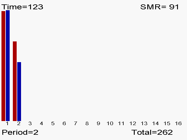
In addition to any key combinations listed below, all the feedback programs respond to the following keys:
Esc exits the program
ALT-P saves a copy of the current screen to the PRINT directory. If the score screen is displayed (see below), it is saved with a white background for more efficient printing.
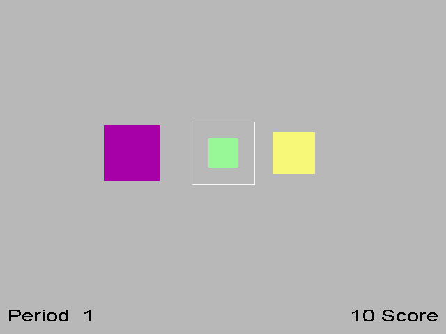
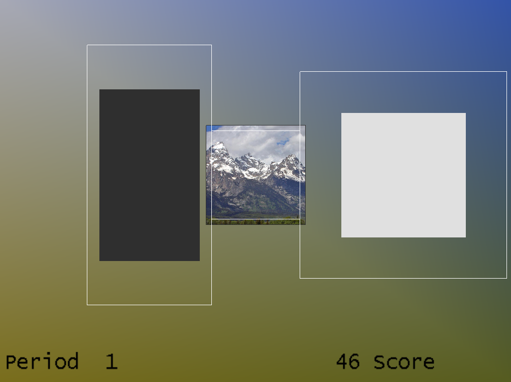
Classic Modern
In the Boxlights game screen, pictured here, the left box represents the amplitude of EEG activity within the low frequency inhibit band; the right box represents the amplitude of the high frequency inhibit bandactivity. The middle box represents the medium frequency (reward band) amplitude. These boxes correspond directly to the bottom three traces on the therapist’s station in 5-trace layouts. A white outline square appears for the reward box. This represents the goal for the band. If the client makes the middle colored box bigger than the white square and keeps it bigger for half a second, while keeping the two outer boxes from touching the white square, they are rewarded with a beep and a score. For 6-trace-with-inhibit layouts, the left box is a rectangle with the horizontal width proportional to the topmost inhibit trace amplitude and the vertical height proportional to the next inhibit trace amplitude.
The colors of the boxes in classic mode are consistent in this and several other games. The low frequency box at the left is magenta; the high frequency box at the right is yellow, and the center box is blue for SMR training and green for beta training (as controlled by the therapist). In the modern mode, the box colors are fixed and the entire background is set based on the current image being displayed in the center box. The image changes at the end of each period.
The goals for the low and high frequency inhibit bands are represented by their distances from the white square. If one of those boxes grows big enough to overlap the white square, rewards are not given. Thus the objective for the client is to make the middle box big and the outer boxes small - that is, to increase amplitude in the selected intermediate frequency (Alpha, SMR, Beta) and reduce amplitude in the outlying frequencies.
The therapist can adjust the relative sizes of the boxes in the Boxlights game by adjusting the scales of the three traces on the therapist station screen. Classic/modern is selected in the game tailoring options.

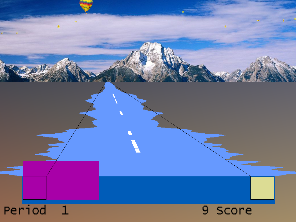
Classic Modern
The Highway game simulates the view from the back window of a car driving down a highway, apparently traveling away from a snow-capped mountain range. The width of the blue or green bar at the bottom of the screen represents the amplitude of the reward frequency band at the moment, just as the center box in Boxlights. Boxes to the left and right represent the amplitudes of the low and high frequency inhibit bands. The near end of the highway varies in width with the central bar (the sides of the Highway are actually a profile of the EEG), but recedes in the distance showing the amplitude over the last seconds. To add interest, and also to give the client a sense of his scoring performance over previous time, a white stripe appears on the center of the highway each time he scores, accompanying the beep and the count. A continuous white stripe indicates continuous scoring performance. To extend that sense of performance, a star appears in the sky with each beep and stays there for the duration of the three-minute training period. A special visual reward occurs when the score reaches 500 or 1000 or 1500 points (or a user-selected value). Similar to Boxlights, the box sizes are a function of amplitudes driven by which layout is used. In this case, the left half of the highway corresponds to the uppermost reward trace and the right side to the lowermost reward trace.
The therapist K key generates a comet (classic) or balloon (modern) reward display.
Classic/modern is selected in the tailoring options.

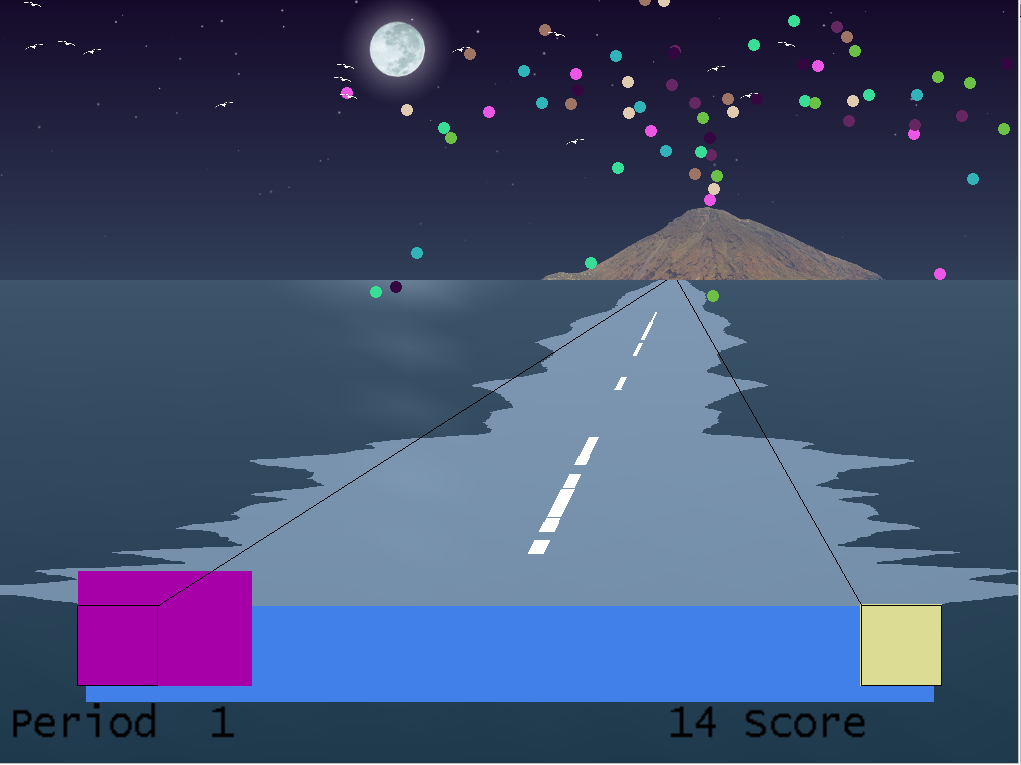
Classic Modern
The Island game is a variation on the Highway game except that the mountain range is replaced by a volcanic island, the stars by birds, and it is the wake of a boat (again defined by the EEG) that disappears in the distance. All reward logic is exactly the same as Highway.
The therapist K key generates a volcano eruption reward display.
Classic/modern is selected in the tailoring options.
Theta-down Highway looks like Highway, but the green or blue bar is totally determined by the inhibit signals with no input from the reward band. The purple box and green/blue bar are tightly coupled. The reward bar is the inverse of the inhibit signals (mostly low frequency). Some special setups are required for this game. The reward threshold (beta or SMR) should be set at about 1 microvolt so that you are over threshold 100% of the time (so feedback is not dependent on it). Set the high frequency inhibit as usual. If the client tenses up, they should be over threshold. The low frequency (theta) inhibit is set so that the client is above threshold about 50%, so beeping will occur about half the time. Either a standard filter or the special filters (2-13 Hz inhibit) can be used. The percentages are set a little different typically, because rather than the wide bar meaning beta or SMR, the wide band is the inverse of theta. That is, if you watch the purple box (theta) it will be identical to the wide band painting highway, except inverse. When theta goes down, the purple box gets smaller, and the wide bar gets wider. The theory is that by positively reinforcing decreased amplitude in the theta band in both the purple and the wide bar – the client gets a possible reward for inhibiting theta.
The therapist K key generates a reward display
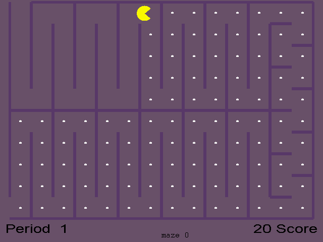
In the Mazes game, an icon moves through a maze eating dots. The speed and color of the icon provide biofeedback information to the client about their brain’s accomplishment of goals. Amplitude in the reward frequency determines the color and speed of the icon; it becomes darker and slower when the Beta or other reward frequency is too low in amplitude; as the amplitude in the reward frequency band grows, the icon becomes brighter and faster. When the amplitude equals or exceeds the goal, the icon is at its brightest and fastest and scores are heard and seen. If amplitude in the low or high frequency inhibit band exceeds its goal, then the icon stops moving and turns black. When the icon reaches the end of the maze, there is a brief rest for the client and a bar graph of their progress is shown. Then a new maze starts. There are thirty different mazes; if more than thirty training periods are given, the early mazes are repeated. Scale selection has no effect visually on the Mazes game, but (of course) affects goal and threshold settings. Optionally, the mazes display can be set to NOT end a period but to just start the next maze. Also, you can optionally start at any maze or use a random selection of mazes.
Mazes is self-timing if the option for continuous operation is not selected. A training period then ends not on a fixed schedule but when all the dots have been eaten or after 200 seconds, whichever comes first. Therefore the red time bars on the score bar chart will vary in height.
This game is a variation of Mazes in which the size of the dots varies (getting larger) with the amplitude of the low frequency inhibit. In some cases, the larger dot sizes are rewarding (instead of inhibiting) and the fixed-dot version should be used instead.
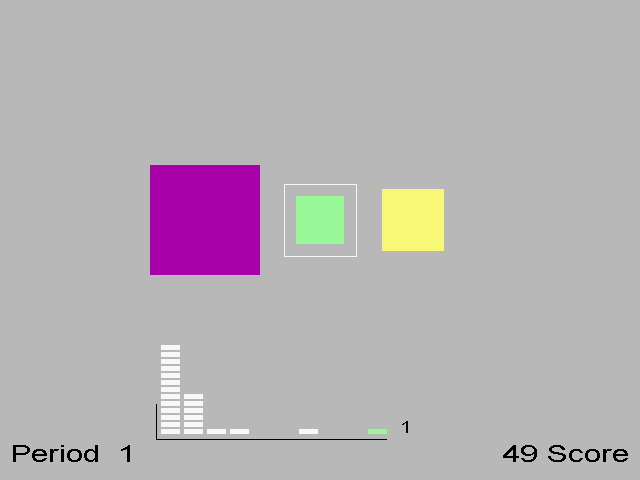
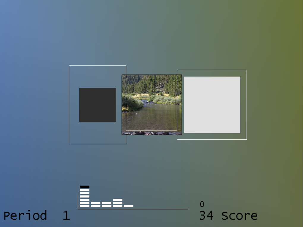
Classic Modern
Jumpbox is a more sophisticated version of Boxlights. It has the same three colored boxes and the score and time reports. It also has a marker chip that moves horizontally along the bottom of the screen that jumps every time the client makes a score. If they make three scores in a row, a chip will jump as far as the third column. If the client reaches ten scores in a row, the chip will reach the last column and turn green/blue. Each chip stops at the point the client fails to maintain all three criteria. Piles of markers further to the right indicate that the client is able to sustain the desired state for longer periods of time. This gives the client added information and an extra challenge. Similar to Boxlights, the box sizes are a function of amplitudes driven by which layout is used. In Modern mode, whenever a chip reaches the last pile the background picture/color changes just as it does at the end of each period.
The colors of the boxes in classic mode are consistent in this and several other games. The low frequency box at the left is magenta; the high frequency box at the right is yellow, and the center box is blue for SMR training and green for beta training (as controlled by the therapist). In the modern mode, the box colors are fixed and the entire background is set based on the current image being displayed in the center box. The image changes at the end of each period.
The 4mation game is an image display game where each reward displays another grid in the image. Options are tailorable for grid sizing (x and y dimensions), grid selection (random, ordered, weighted), sounds played, a success sound on filling all the grids, user selection of image directories, etc. A special key option on the game computer (Alt-D) can be used to cycle through the pictures during the time that the credits are shown on the screen (i.e. before pressing F5 for the first time). User pictures can be .BMP, .PNG or JPEG files. Note that many cameras provide files with .JPG extensions that are NOT JPEG files but EXIF files – an attempt is made to translate these also.
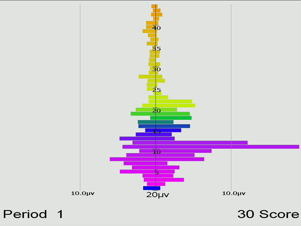
The Spectral Mirror display shows amplitude of the EEG signals at various frequencies. Above is shown the display with two channels of information displayed. Below is a mirrored display showing only one channel but reflected on both sides of the center axis.
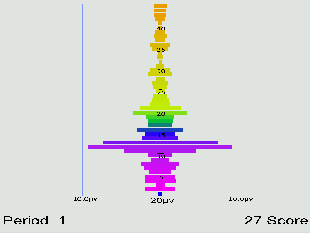
The therapist controls the horizontal scale for this display whose data is the real-time spectral data used for the Therapist displays.
The long-term display shows either or both of EEG data and peripheral data.
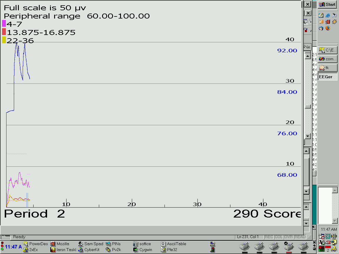
The display above shows both kinds of data in the slow display mode where the entire session width represents the screen width (as shown on the time scale at the bottom). There are different scales for peripheral and EEG data. Notice that the frequency bands are shown with the related color code. Below is shown the display with no peripheral data displayed (in the medium speed, 10 minutes across).
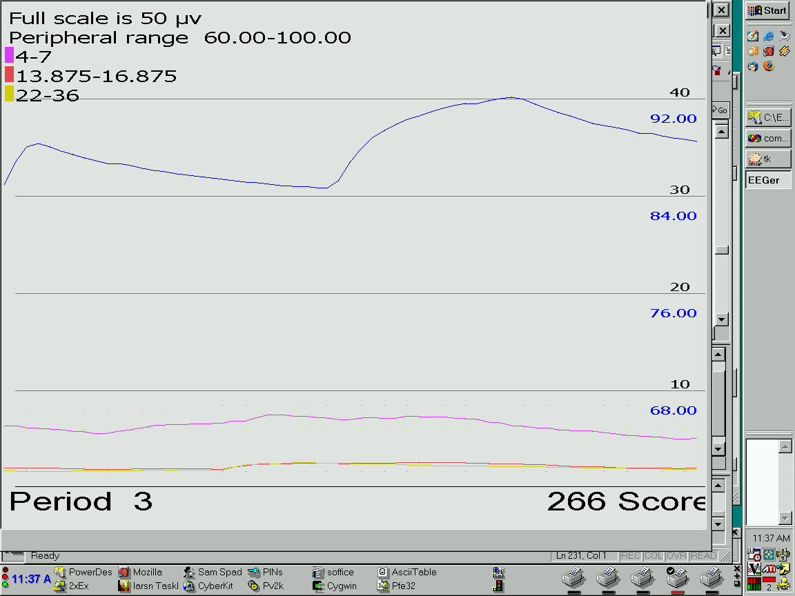
Here is the display shown using the fast speed display (one minute across):
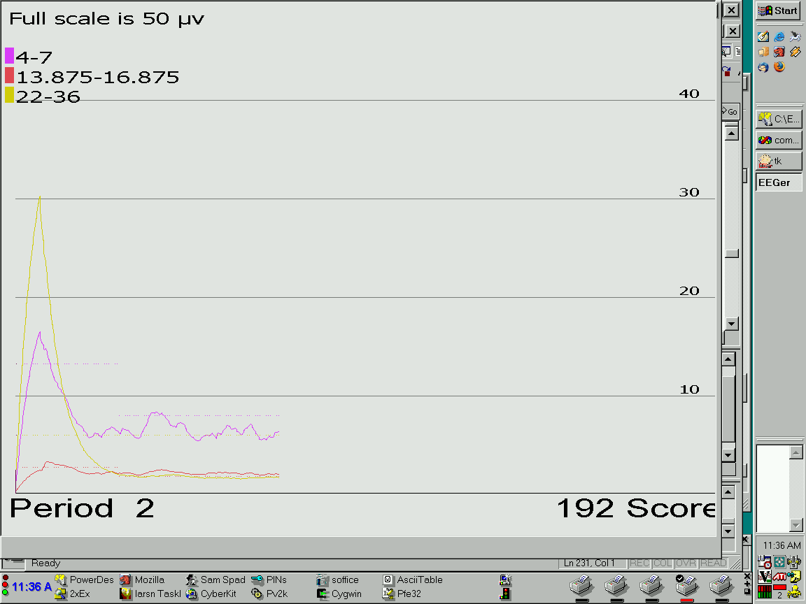
The EEG threshold line displays are also controllable by the therapist.
The optional Iris feedback display provides a background picture/color masked by one to four elements so that there is a display available for multiple rewards. Background pictures come from a 4mation picture set. The rewards can be driven by normal EEGer reward modes or by various zscore modes. The single reward channel display looks like this picture:

The four channel reward mode looks like this picture:

Each reward channel controls one element, masking the picture behind as the rewardable state changes for each reward stream. Mask colors are controlled by game tailoring options.
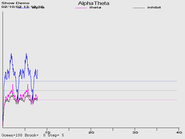
The feedback consists of two environmental tones signaling the general range of the client's state-of-relaxation, and tones that signal momentary bursts of EEG in one or the other reward band. The alpha environment (trace 3) is a running stream, and its tone is a high-pitched bell. The theta environment (trace 2) is ocean waves, and the theta tone is a low-pitched bell. As relaxation deepens, the ongoing environmental sound will cross-fade from stream to ocean and low-pitched bell tones will replace the high-pitched tones. In cases where both frequency ranges are over threshold at the same time, the system is biased toward signaling the trace 2state. If the unbiased option was selected in game tailoring, the trace with the highest above-threshold value is selected.
Since the client station screen is not needed for visual display, it is used to display extra therapist information in the form of a line graph depicting amplitude over time for the two reward traces and the inhibit trace.
Alpha-Theta Volume Controls
The default volume levels for the background sounds and reward tones are set to a percentage value.
Theta (ocean wave) volume
Alpha (babbling brook) volume
Alpha reward (Bell) volume
Theta reward (Gong) volume
The next-to-last option adjusts the master volume. The last option adjusts the fade or rate-of-change speed used when switching between the wave and babble sounds. The “Edge rate border” controls the percentage of range (near the edges of the transition) where a double fade rate change will be used.
At the bottom of the Alpha-Theta display are the "names" of the sounds along with the relative percentage of the two signals (alpha and theta). When a tone is generated, the appropriate "name" for the tone displays during the playing of the tone. The "Step" value is the current setting of the fade step value which controls how rapidly the environmental sounds transition.
The main menu program is only used in 2-computer mode on the game/client computer. The main menu program monitors communication with the Therapist computer and responds accordingly by dispatching whichever feedback/support program is commanded by the Therapist computer. F1 brings up/drops a help menu display. Alt-Tmay be used to bring up a tech support menu used to simplify technical support.
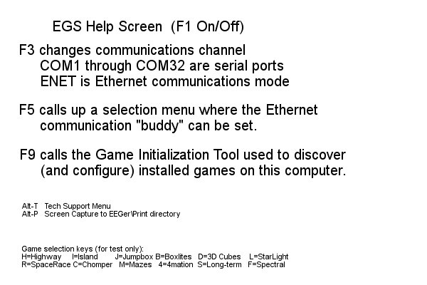
A spinning "propeller" is shown in the upper left corner as a confidence factor (reporting that the program really IS running). The display shows installed Beta/SMR games and is updated by saving the result of the game discovery tool.
The Esc key is used to exit the menu program back to the Windows Desktop.
The F3 key is used to change the communications channel used to "listen" to the Therapist computer. Pressing F3 causes selection of the "next" available channel and the selected channel to be displayed in the upper left corner (in red). Each F3 press causes the next channel to be selected cyclically. The Ethernet selection is one of the possible communications channels (but needs some extra setup – see the F5 option).
If the communication with the therapist computer/program is working, the communications channel will be displayed in white. If communication is NOT working, the display will be in red letters.
Alternately, the F5 key can be used to bring up a menu of channels and Ethernet options.
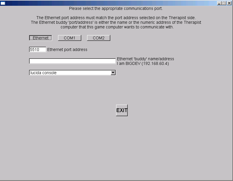
On this menu, the appropriate Ethernet port address (which MUST match the therapist preference setting) can be set. The EGS font selection (for 2-computer operations) is made on this screen. Selecting the font name popup window gives a selection similar to this:
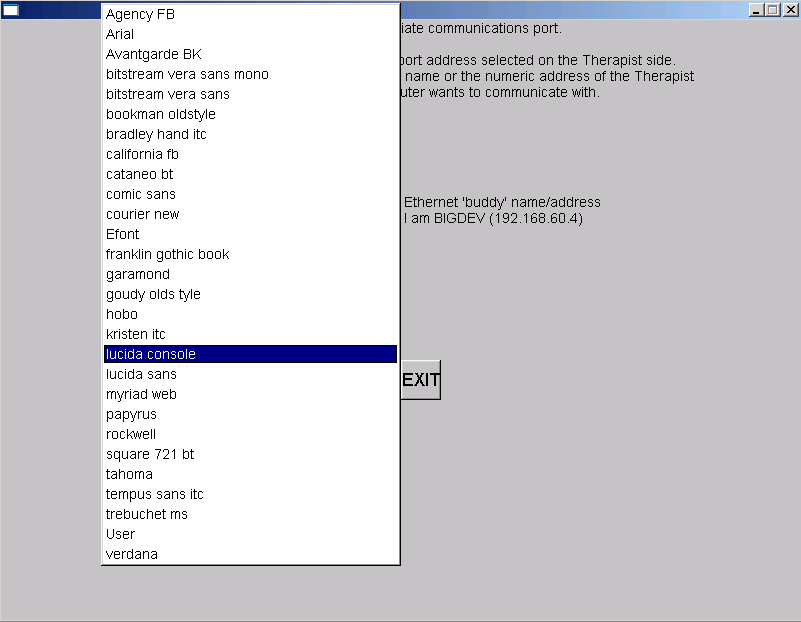
Please experiment with these font selections to find one suitable for you. Not all selections appeal to everyone.
The F9 key can be used to start the Game Initialization/discovery tool directly from the game menu.
The ALT-P key combination saves the current display screen to the PRINT directory.
The feedback loop begins with the client. Sensors 'pasted' to the client's head pick up microvolt-level EEG signals which are amplified and converted to digital voltages by the A/D subsystem at a nominal rate (typically 256 Hz).
The samples are converted to equivalent peak-peak voltages. All filters in the software are Infinite Impulse Response (IIR) filters. The raw samples are lowpass-filtered by a 40 Hz filter to remove 60 Hz ambient noise. The clinician adjusts a threshold voltage value to inhibit the data in the presence of muscle (EMG) artifacts. The resulting lowpass signal is fed to a number of 'streams' of processing which are very similar, although some are labeled “Inhibit” and some labeled “Reward”. A typical test run uses two inhibit streams and one reward stream.
In each stream, the lowpass signal is bandpass-filtered into various frequency bands (of the clinician's choice) using IIR digital filters. The filter output is fed to an exponentially-weighted moving average filter which produces a short-term average (peak- to-peak) voltage for further use. The time constant of the averaging filter is selectable but is usually 0.5 seconds. The moving average goes two places: directly to the client (game) display software (for visual stimulus) and to a comparator. The comparator produces a threshold-exceeded signal whenever the clinician-adjusted threshold voltage is less than the current moving average of the stream. This logic is shown in Figure 1.
All the threshold-exceeded signals are processed by the reward decision logic which declares a 'client reward' when all streams defined as “Inhibit” are below threshold and all streams defined as “Reward” are above threshold. The client aural reward rate is further limited to no more than 2 Hz (so that each sound can be separately heard). The client reward command is sent to the client software to create an aural stimulus.
The visual feedback is independent of the aural feedback (except that they are both based on relative amplitude/threshold values). The client software plays a prerecorded sound file (usually a short ¼ second beep) whenever a reward is commanded, giving aural feedback to the client that all clinician-specified (amplitude) conditions were being met. The client software also draws simple graphics images giving a continuous display of the ratio of amplitude to threshold for each stream of data. The client visual display depends on the particular “game” chosen but all act similarly. The simplest presentation is of three boxes as shown in Figure 2. An outline is drawn for each box representing the “threshold” value. A color-filled square is drawn representing the current “amplitude” of the stream of data. Instructions to the client consist of telling them to make the 'inhibit' squares smaller than the outlines and the 'reward' square bigger than the outline. The 'reward' square is in the center and the inhibit squares on either side of the reward square.
The client's EEG response to the aural/visual signals is then sensed and fed back into the loop.
Figure 1.
Figure 2.
The terms listed are defined here to minimize confusion over the loose use of previous terminology.
10-10 electrode system A system of electrode placements for acquisition of scalp EEG. The “10-10” title means that the placements are every 10% around the circumference of the head (like a hat measurement) and every 10% of the distance from nasion (front) to inion (back) over the top of the head. Defined by the placement shown in Figure 1
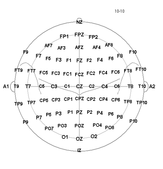
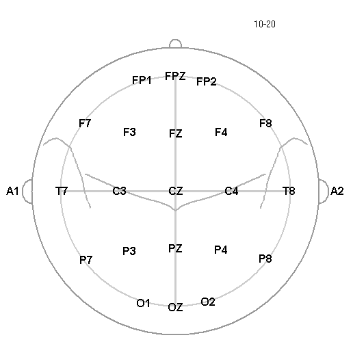
Figure 1. 10-10 modified Figure 2. 10-20
10-20 electrode system of the International Federation– Most widely used electrode placement for acquisition of scalp EEG. Defined by the placement shown in Figure 2.
Activation – Excitation/inhibition; referring to operant conditioning process.
Amplifier – A device that draws power from a source other than the input signal and produces as an output an enlarged reproduction of the essential features of its input.
Analog to digital converter (A/D)– A device that changes an analog signal to a digital signal of corresponding magnitude through discretization.
Artifact – any distortion of the EEG signal from any physiologic source other than the brain or any non-physiologic source that may interfere with the interpretation of the signal.
Average value (P-P) – The “average value” traditionally used in neurofeedback is actually the “equivalent peak-to-peak” voltage value using the assumption that the signal being measured is a sine wave. The normal method of calculation is to sum the absolute voltage values of each signal sample, divide by the number of samples, and 2*√2 to get the peak-to-peak equivalent.
Band – see EEG Activity definition. Actual frequency values are recommended instead of names due to the variation in definitions.
Baseline – status of brain activity when not engaged in a feedback/operant conditioning process.
Channel – each physical input measurement is one. It may take several 'connections' to a client for each physical input (such as 3 electrodes). A channel is comprised of the electrode(s), preamplifiers, amplifiers and encoders that make up a measurement path.
Client - Person who is receiving neurofeedback (i.e.,is connected to a neurofeedback system); person from whom EEG signal is being acquired.
Clinician – Person responsible for ordering (prescribing) as well as interpreting and making clinical decisions about neurofeedback; oversees the neurofeedback session. This person is also responsible for the technician.
Coherence – Measure of phase relation of two processes at a specific frequency band.
Component – A major element of a neurofeedback system (acquisition, software, etc.)
Corner frequency – Frequency designating the meeting between the transition band and passband; frequency at which gain crosses -3dB (typically).
DC level – The average value of the zero-crossing points of a periodic wave. If not zero, this means that there is a steady-state offset of the signal from its "ground" reference point. It is computed by summing each sample and used to move the incoming signal to a point where positive and negative excursions occur around a "zero voltage" point.
Digital filter - A linear computation or algorithm performed on a selected series in the form of an input signal that produces a new series as output.
EEG activity / frequency bands (Alpha, Theta, Delta, SMR, Beta, Gamma, etc.) -
There are many definitions for naming EEG data bands. Actual frequency values are preferred but typical names/ranges (from Spehlmann ) are:
DC-EEG: < 0.1 Hz
Delta: 0.1-<4Hz
Theta: 4-<8Hz
Alpha: 8-13Hz
Beta: >13-30 Hz
SMR (sensorimotor rhythm) – rhythm seen in signals over the sensorimotor cortex; usually considered in the range 12-15Hz
Gamma: > 30 Hz (particularly 36-44Hz)
Another typical set of names/values is:
Delta 0.1 to 4 Hz
Theta 4-7.5 Hz
Alpha 7.5 – 13 Hz
Beta 13-30 Hz
Gamma 30-50 Hz
SMR(low beta) 12-15 Hz
Beta(mid beta) 15-18 Hz
High Beta > 18 Hz
Electrode – the flat or cupped piece of metal used to sense
electrical energy;
also has a wire on it to attach to an amplifier or
preamplifier.
Electroencephalograph (EEG) – instrument for recording the electrical potentials produced by the brain by the use of electrodes.
ERP (Event Related Potential) – evoked activity of the brain related to a sensory stimulus; derived by averaging EEG activity with respect to stimulus onset.
FFT (Fast Fourier Transform) – computational technique that reduces the number of mathematical operations in the evaluation of the discrete Fourier transform (DFT) to N log2N; where DFT is a transform for Fourier analysis of finite-domain discrete-time function; used to convert the input signal from time domain to frequency domain.
FIR (Finite Impulse Response) – An FIR filter is a non-recursive method for extracting frequency information from a time-sampled input. FIR filters typically have good phase accuracy but poor amplitude fidelity. FIR accuracy is a function of the number of samples used.
Frequency response –
The portion of the frequency spectrum that can be sensed by a device within the specified limits of amplitude error.
The range of frequencies over which an amplifier responds within the defined limits of amplification or signal output.
Range or band of frequencies to which a unit of electronic equipment will offer essentially the same characteristics.
Ground – The "ground" is an isolated current-limited input used to provide a "zero voltage" point with respect to the signal being measured against its reference.
Haptic – of or pertaining to a sense of touch; tactile.
Hertz – The measurement unit of cyclic activity, abbreviated as Hz.
IIR (Infinite Impulse Response) – An IIR filter is a recursive method for extracting frequency information from a time-sampled input. IIR filters typical have poor phase accuracy but good amplitude fidelity.
Impedance– opposition to the flow of a cyclic (alternating current) current through the interface between an electrode and the scalp. If measuring, must be at least 500 ohms and less than 10,000 ohms between any two electrodes.
Layout– arrangement of traces with implied connections of data to game display
Operant conditioning – a form of learning or modifying behavior during which an individual modifies its own behavior due to the consequences of that behavior. Neurofeedback uses responses based on EEG data as the stimulus for the desirable rewards (consequences).
Passband – range of frequencies, or frequency band, for which a filter passes the frequency components of the input signal.
Peak – Highest (voltage) amplitude of a signal
Peak-Peak Voltage – The peak-peak voltage is the difference between the most positive and negative values of a cycle of a (sine) wave. All EEG amplitudes are reported in peak-peak voltage. For complex EEG waves, an average value is computed and the peak-peak voltage is inferred from that result.
Phase – angular relationship between two waveforms.
Reference – Depends on usage (see Signal).
Ripple - variation in amplitude of frequencies passed through a filter
QEEG – Mathematical analysis of electroencephalograph waveforms used to extract discrete data and output specified parameters. The EEG data can be algorithmically analyzed by the size, frequency, and/or the locality of the electrical activity. These datasets can be reported either absolutely or relative to some other dataset. The data is typically presented in tabular form or as topographic maps.
Rolloff – transition region between passband and stopband; usually reported as a function of logarithmic frequency in decibels per decade or decibels per octave.rolloff - rate at which attenuation occurs at frequencies outside a filter's pass band. The higher the rolloff value (measured in decibels), the narrower/sharper the attenuation is outside the pass band and the more computation required.
Example:
Shown in Figure 3 is a typical filter diagram with frequency as the horizontal scale and relative amplitude as the vertical scale (adjusted to unity).
Ripple is the amplitude variation between points A,B, and C of a pass band.
Rolloff is how fast the attenuation takes place (as frequency changes) measured to the 30 db (50%) point (D) from point C. There is also rolloff on the low edge of the pass band.
Edge frequency is point A or C.
Center frequency is 4.5 Hz (midway between A at 2 Hz and C at 7 Hz).
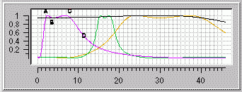
Figure 3.
Session – Single administration of neurofeedback training to the client by the clinician or by the technician but overseen by the clinician . There may be multiple electrode placements and/or shaping actions within a single session. A neurofeedback regimen may necessitate multiple sessions.
Shaping – The use of significant features of the EEG waveform in the operant conditioning process to alter the EEG waveform. Shaping implies control over which elements of the transformed waveform are used and how they are applied in producing the operant conditioning stimulus.
Signal – a voltage (measurement) varying with time; always
made with respect to something (differentially). ProComp
preamplifier leads are called Signal+ (yellow) and Signal-
(blue).
Other amplifier leads may be called Signal (yellow) and Reference
(blue) or some other colors.
Slow Cortical Potentials (SCP) – A feedback signal generated from lowpass filtering of artifact-corrected EEG using a sliding averaging window. The frequency range is usually considered 0-2 Hz.
Smoothing – a method of limiting the effect of short term excursions of data samples. The method used in EEGer is Exponentially-Weighted-Moving-Average filtering.
All
EEGer smoothing is:
SMOOTHED=CURRENT_SAMPLE*(k) + SMOOTHED*(1-k)
where k
is something like
k= 1/(time_constant*samples_per_second)
Spectral – A frequency versus (power) amplitude display of data. The frequency data is generated from a moving FFT computation.
Stage – one piece of the session process, usually a particular action/operation.
Stopband – range of frequencies attenuated by a filter with some specified attenuation.
Stream– each processed entity is one; may be made up from one or more channels
Technician - Operator of neurofeedback system while the client is connected to a neurofeedback system.
Threshold – term used to describe the setting of a point at which a transformed value is acted upon (such as artifact detection).
Trace– a graphical display (strip chart display) of a stream.
EEG Education & Research Technical Support recommends the following steps to optimize the performance of EEGer Neurofeedback Software.
PERFORM THESE STEPS ON COMPUTERS WITH PERFORMANCE PROBLEMS:
Windows 7+ Video Settings:
Click Start. Right-click on Computer in the menu and select Properties from the menu. System properties should be displayed.
Click on Advanced System Settings
Click the Advanced tab, then the first Settings button for Performance Settings.
On the Video Settings tab. Select “Adjust for best PERFORMANCE” and click OK.
Windows 7+ Video Resolution:
Click Start and select Control Panel.
Select Appearance and Personalization
Under Display, select Adjust Screen Resolution
Screen area/resolution minimum requirement is 1024x768 with 16-bit color. The best setting depends on the computer equipment, but we generally stay at 1024x768 pixels, 32-bit color.
NOTE: If you are running a dual monitor setup, make sure that the Multiple Displays option shows “Extend these displays”.
If you make a change, click OK. Be sure to respond to any prompts to confirm the change or the system will automatically revert to the previous setting (It does that in case you couldn’t see with the new setting.)
PERFORM THESE STEPS ON ALL NEUROFEEDBACK COMPUTERS
Power Management Settings:
Click Start and select Control Panel.
Double-click the Power Control Panel. (For Toshibas, use the Toshiba Power Management Control Panel.)
Set all options to Never turn off or to a high enough setting that it will not occur during a session. Note: This is particularly important for a Game computer since the keyboard and mouse are rarely used. (For Toshibas, you’ll need to select the Power Save Mode option, such as Full Power, and edit the details for that Power Save Mode).
Click OK to save changes.
Screen Saver:
Click Start and select Control Panel.
Click the Screensaver tab.
Set the name to “None” or set the Wait time high enough to avoid the screensaver during a session. Note: This is particularly important for a Game computer since the keyboard and mouse are rarely used.
Click OK if you’ve made a change.
Windows Device Setting for USB Ports:
Click Start and select Control Panel.
Double-click the System Control Panel.
Click the Hardware tab, then the button labeled Device Manager.
In the alphabetical list, locate “Universal Serial Bus Controllers” and double-click that text. (You may need to use the scroll bar at the right to get down to that entry).
For EVERY “USB Root Hub entry”, follow these steps:
Double-click USB Root Hub
Click the Power Management tab at the right.
Click the checkbox so it is Unchecked.
Click OK.
Close all windows.
Virus Protection and Firewalls:
Follow the manufacturer's instructions to disable virus protection and configure your firewall to avoid interference during a neurofeedback session. If you access the Internet with the system, disable virus protection only when actively running a session.
Currently, Microsoft Security Essentials may be used as an antivirus program since it does not appear to degrade performance during neurofeedback sessions.
Wireless Internet Devices
We recommend that you disable Wireless access to your computer when running a neurofeedback session. Some computers have a switch to do so. For others, go to the Windows Device Manager under Network Adapters. Right-click the Wireless adapter and select Disable.
System Memory
If the
system has the minimum requirement of system memory to run the
operating system, you may wish to add additional memory. If the
system uses Integrated Video or an AGP video card, the video may
share the system memory. Increasing the system memory may be
necessary for optimal performance.
EEGer Home Use operationissimilar to Clinical operationin its use of the same hardware and software to perform the neurofeedback functions. Bothare designed toallow remote supervisionof a home-user and provide live neurofeedback session remotely.
Ahome-user(or sometimesacaregiver) must first be trained by thetherapist in the operation of the HomeUse system. The client training screens and software are identical to the therapist’s clinical machine. On a clinical system, the therapist establishes a treatment period and number of sessions for each Home User by creating a Home Use client file(also called as EKC file, which is apersonalized Home-use profile). Each client is limited to a number of sessions to be run in a given time period using the kind of training/sessions(Alpha-Theta or BetaSMR) established on the clinical system. Updates for the Home Use Session Plan are obtained from the supervising clinician (knowncalled as EKR files).
The functions of the HomeUse system are almost identical to those in the clinical system. The only differences in operation are the restrictions on changing the session plan and the application of date or session count control to the use of EEG biofeedback. Some menu options will NOT appear on a Home Use system, while it includes some that do not appear on a clinical system.
Home-use client file Installation:
An EEGer Home-Use system will only allow live neurofeedback sessions on an installed Home-use client. To installa home-use client:
Plug in the EEGer dongle to your computer's USB Port. If you have an EEG amplifier/acquisition device, connect it the computer (either by Bluetooth or USB)
Click EEGer on the desktop shortcut icon or on your
start menu list. You will observer an EEGer start animation while EEGer is
loading. Skip to step 4 if EEGer is already
running.

It will prompt you for the EEG Acquisition device connected to your computer. EEGer may inform you that its unable to find an amplifier/device. Select “OK”
When you select OK, EEGer main screen will be
brought on top. you (home-user) must download
a Home-use client file from the cloud using EEGer’s
Download HU-file from cloud
option by navigating to Client>Home-use>Download HU file from cloud on
the Main EEGer screen.
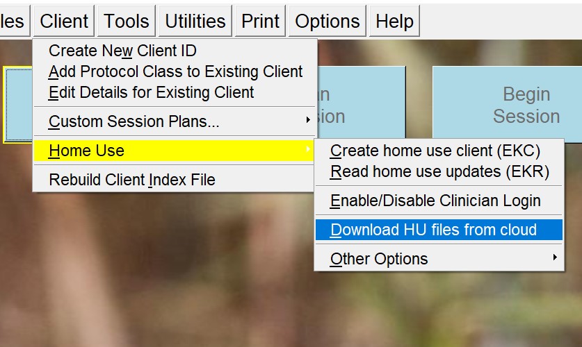
A busy screen will pop
up while EEGer is connecting to the cloud. After a brief moment, a
list of files will appear on your screen.
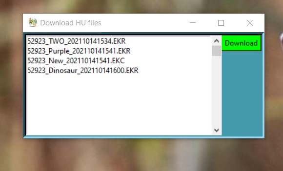
Select the EKC file with a file description (xxxxx_testName_xxxxxxx.EKC as an example where the file description is testName) instructed/described by your supervising clinician. Download the file by selecting the Green Download button.
You will notified with the status of your request. Make sure you record the final message displayed. It will tell you the location of the file you just downloaded. You will have to use this information in the next steps. Close the utility now.
Note: If you have selected a single EKC or EKR
files, you can skip to step #10 for verification as EEGer will
automatically insta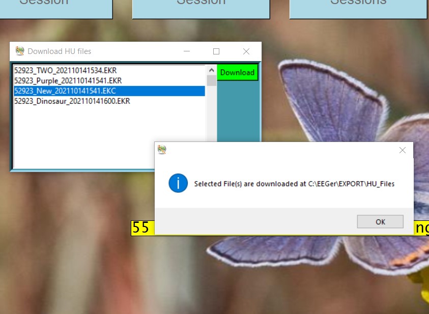
ll and update home-use client (only from EEGer 400w and
above).
Now
to Install the Client file. Navigate to Clients>Home-use>Create Home-use
client on
the main EEGer screen and select it.
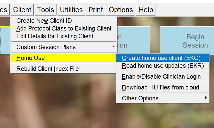
You will observe a File Browser window that just popped up. Navigate to the place your EKC (Home-Use client) file is saved (downloaded in step 7). Double click on it or select it once, and select open button. A success message will appear on your screen.
Note: You can download the same file multiple time. However, you can only install the EKC once. In the event you cannot locate the downloaded file, you can repeat steps 5-7 again. The download process will display the location of your Home-use file.
To verify your installation, Select “Select Client” button on the EEGer main screen. Double click on “A client already on computer” when a dialog box is displayed. You will be shown a list of clients and their Session protocol class (Protocol classes are EXP, SMR and AT). If you observe a ‘[HU]’ on the beginning of the home-use client name/description, your first home-use client/profile is installed. You can select it and click on ‘OK’ button.
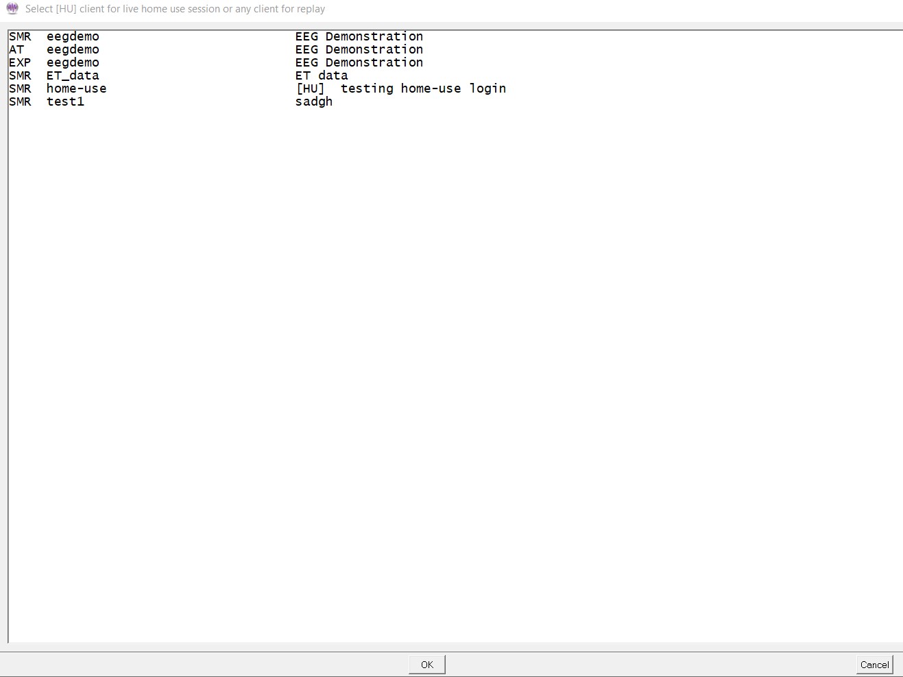
You will be brought to EEGer main screen and on
the center of the screen, EEGer will display the number of session
you are authorized to complete and the date of
expiration.
How to Run a Session
The EEGer Dongle (USB key) must also be attached.
Prep and attach the sensors (electrodes) as instructed by your supervising clinician.
On the Home Use system, double-click the EEGer icon. (Two-computer systems: start EGS on the game computer first.)
Click Select Client then Double click on “A client already on computer” when a dialog box is displayed. This will load the EEGer client information from the Home Use Client file. Select the Client ID/Protocol to use for the session.
Note the Dongle and Remote Sessions remaining and if there is a warning about an expiration date on the main display.
Click Begin Session.
Select a game and click OK. (refer to Tailor Installed Games for game customization)
Confirm the game selection and turn on the amplifier/EEG Acquisition device, if necessary.
Adjust the scale on the raw trace, if necessary.
Press PgDn to highlight the raw trace (e.g., Channel A is the first line on the EEG screen).
Press F9 to move to the Scale value field.
Press + or – to adjust the scale. (Increasing the scale value decreases the size of the wave.)
Press Enter twice to complete.
Observe brainwaves. Blink or clench teeth to see how the “artifact” is displayed in the raw EEG trace. Adjust the thresholds on the raw trace, if necessary, to keep the artifact out of the training, but not too closely that they remove real EEG.
Press PgDn to highlight the raw trace.
Press + or – to adjust the threshold boundaries.
Press Enter once to complete.
Set the scales and thresholds for the lower traces. With no lines highlighted, press F9 to auto-adjust the scales. Then, press F11 if adjustment for goals is needed. Follow the steps above to set scale or goal threshold for any individual trace.
At this point you can still back out without counting a session by pressing Esc.
Press F5 to start feedback. (Single-monitor: Press the Space Bar to switch to the Game display.)
Enjoy the Game.
Press Esc when finished.
EEGer Remote Use Updates
How do I know when I need an update?
How do I get an update?
Insert the EEGer Dongle and open the EEGer program.
Click Select Client then double click on “A client already on computer” when a dialog box is displayed. This will load the EEGer client information from the Home Use Client file.
Select the client name/protocol from the client list.
Note the information displayed on the main screen (Figure 1). Yellow messages are “warnings” that one of the controls is about to expire. Red messages mean you are not able to run a live session until you update.
If you see that either Dongles Authorizations or Home Use Sessions/Days are about to expire, contact your supervising clinician to request the appropriate update(s).
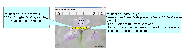
Home Use Expiration Details
Updating EEGer Dongle Authorizations
Normally EEGer downloads keyfile updates automatically. However, if EEGer Dongle authorization file is shared to the Home-user via email or other source of file transfer, authorizations must be installed manually.
Authorizations are added to the EEGer Dongle by installing a special keyfile obtained from EEG Store(supervisor’s permission is required for purchase). You may receive the keyfile from the cloud downloador as an email attachment.
Attach your EEGer Dongle to the Home-use EEGer computer. Double-click the EEGer icon.
Click “OK” for notification after which main EEGer will be displayed.
To install the Dongle Authorization update from EEG Store, Navigate to the Files> Read EEGer keyblock file option and select Read EEGer keyblock file on the file browser.
Updating the Home Use Client
A Home-user (you) can download an update file (called an EKR file) using the same download utility used in Home-use client file installation. Your supervising clinician must already have uploaded EKR file to the cloud.
Plug in the EEGer Dongle to your computer's USB Port. If you have an EEG amplifier/acquisition device, connect it the computer (either by Bluetooth or USB)
Click EEGer on the desktop shortcut icon or on your
start menu list. You will observer an EEGer start animation while EEGer is
loading. Skip to step 4 if EEGer is already
running.
It will prompt you with the EEG Acquisition device connected to your computer. EEGer may inform you that its unable to find an amplifier/device. Select “OK”
When you select OK, the EEGer main screen will be brought on top. You (home-user) must download a new Home-use client file from the cloud using EEGer’s Download HU file from cloud option by navigating to Client>Home-use>Download HU file from cloud on the main EEGer screen.
A
busy screen will pop
up while EEGer is connecting to the cloud. After a brief moment, a
list of files will appear on your screen.
Select the EKR file with a file description (xxxxx_testName_xxxxxxx.EKR as an example where the file description is testName) instructed/described by your supervising clinician. Download the file by selecting the Green Download button. You will notified with the status of your request. Make sure you record message displayed. It will tell you the location of the file you just downloaded. You will have to use this information in the next steps.
Note: You can download the same file multiple time. However, you can only install the EKR once. In the case you cannot locate the downloaded file, you can repeat steps 4-5 again. The download process will display the location of your Home-use file.
Once you are back on the main EEGer screen.
Navigate to Clients>Home-Use>Read Home use
updates (EKR) and select. Double click on “A client already
on computer” when a dialog
box is displayed. You will be shown a list of
clients.
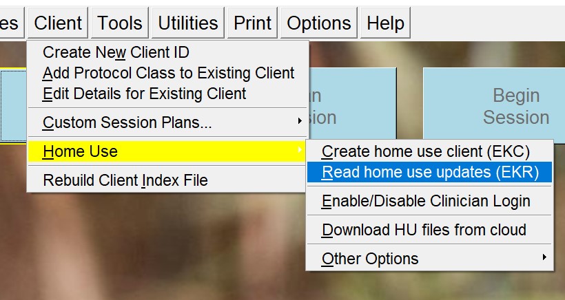
Select the client to be updated by the downloaded EKR file. Notice your valid Home-use client will have a “[HU]” as the full client description.
You will observe a File Browser window that just
popped up. Navigate to the place your EKC (Home-Use client)
file is saved (downloaded in step 6). Double click on it or select
it once, and select open button. A success message will appear on your
screen.
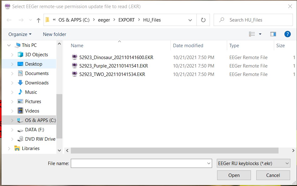
Note: You can download the same file multiple times. However, you can only install the EKR once. In the case you cannot locate the downloaded file, you can repeat steps 4-8 again. The download process will display the location of your Home-use file.
You can verify by selecting the client again on the Main EEGer screen (step 4)
Updated session information can be viewed either on the center of the main EEGer screen or in the plan session screen.
Refer to Plan for more technical information on session plan configuration. However, without update session permission configured, Home-user will not be able to change any aspect of session plan
Email Attachments for Updates:
For either type of update, save the attached update file to your Windows Desktop or to a disk (DO NOT OPEN the attachment). If your email computer is not your Remote Use system, copy the file to a disk to move it to the EEGer Remote Use computer (e.g., use your Remote Use USB Flash drive). Update files must be installed using the appropriate selection from the Files menu in EEGer and cannot be installed by double-clicking the file.
Before the client can use the system, it is the clinician’s responsibilityto train the client (or caregiver) in the operation of the Home-Use system. A Clinical system must have “Supervise RemoteUser” keyfile enabled (SUPERV-R) to initialize a home-use client file (EKC)and renew a Home-use client file (EKR). A Home-use Client file (EKC) can only be created on a clinical system by creating a new client (refertoCreate New Client ID) intended for Home-use and adding home-use session permission, limitations and other home-use related feature (refertoCreate new Home-use Client (EKC)).
You (supervising clinician) can upload the “Home-use client” file (EKC) using the HU-upload utility (refertoUpload HU-files to Cloud) or share it with any file transfer application. These Home-use files arethen downloaded and installed by the Home-user using HU-download utility (refertoDownload HU file from cloud).
Supervising Clinicians have the ability to add/modify/update Home-use client configurations by creating an EKR file any time (refer to Renew Home-use session plan (EKR)). Furthermore, Supervising clinicians have a provision on making legacy Home-use feature (before 440r) by navigating to other options under clients>home-use optionson the main EEGer screen.
Session counts and expiration dates for individual clients using the Home Use system are controlled by YOU(the clinician), through the purchase of Dongle Authorizations and Creation of EKC/EKRfiles. Home-use client filesconvey expiration, session count, and session plan information to the Home Use computer. The EEGer license dongle contains the number of sessions available to be accessed.
HomeUse System Requirements
Provided by EEG Store
EEGer version 4.4.0(t) or earlier versions (with limited capability)
EEGer license dongle with programmed Dongle Authorizations
EEGer Home Use license keyfile
Provided by You – the Supervising Clinician
EKC and EKR
files containing the training session plan(s), number
of Home Use sessions
permitted, expiration date, & clinician login password (optional).
Training in the operation of the EEGer system;
including sensor placement, confirmation of the
amplifier connection, how to read the EEG and adjust training
parameters.
Requirements to Run a HomeUse Session
EEGer version 4.4.0(t).
EEGer Dongle Authorizations available on the EEGer license dongle
Home Use sessions available on the
Home Use client file as
specified in the
Home Use session plan
Date must be prior to the
expiration date
for Home
Use Sessions as specified in the
Home
Use session plan
Clinician Procedures
The recommended procedure for a client who has acquired a Home Use system is for the client to continue to be seen in the office periodically. However, inEEGer 440t, Home-use clients can receive remote updates to their client files without visiting the office. The Home-use client cangenerate a Consultation export of the HU-client and email it to youfor each office visit. You (supervising clinician)may want to review the data before updating the training session plan (by making a new EKR and uploading it).
STEPS FOR SETTING UP HOMEUSE TRAINING
Order the EEGer system from EEG Store with a specified initial number of dongle authorizations. If the system is shipped to the client, they may set up the system prior to coming to the office for training. Clients who purchase a “kit” will have to do all of the installation and setup.
Create the ClientID and custom Plan Session for the desired training of each client who will use the remote system using your CLINICAL system.
Create/Initialize a new Home Use client file (EKC file) for each client who will use the Home system. Be prepared to enter the number of sessions allowed and expiration date for the session plan (Default is 45 sessions in 45 days. You can change the number of sessions or expiration based on your treatment plan.)
Train the client in the use of EEGer and provide them with the Home-use client file(s) for home use.
Review data on the consultation exports.
Update/Renew the Home Use client to permit additional sessions, change the session plan, or extend the expiration date for the Home Use plan by creating an update file that can be installed by the home-user.
Update the EEGer dongle by requesting additional Dongle Authorizations from EEG Store as necessary.
Initialize the Home Use Client Disk
Use the Home Use file upload utility to share all created Home Use files with the Home-user
A. SET UP THE CLIENT AND SESSION PLAN
On the CLINICAL Therapist system, go to the Client menu and select Create Client.
Follow prompts to enter a Client ID, full name, and birth date. Click OK after each.
Select protocol class for the client: BetaSMR, Alpha-Theta, or Experimental.
If desired, create additional protocol classes using Add Protocol Class to Existing Client from the Client menu.
Click Select Client and choose the Client ID/class entry for the Client ID to set up session details.
Click Choose Layout then click the button to select the number of EEG traces for the training display.
Click Plan Session to set up protocol details.
Repeat steps 3-5 if you want to add another protocol class to the client’s training plan.
B. CREATE A NEW HOME USE CLIENT (EKC) file
From the Client menu, select Home Use Options-Create a new Home-use Client. (NOTE: Versions prior to EEGer 4.4.0(t) have slightly different menu options text)
Select the client name from the list of clients.
Create the Home Use Plan
Select the client Class.
Select the desired Layout.
Set up the session count and expiration. You must know the client’s EEGer dongle number for proper setup.
Default settings are 45 sessions and 45 days. Adjust the Remote Session count and expiration date as you see fit based on your treatment plan. Make a note of the allowances in preparation for future updates to the Home Use Plan. You can add Clinician Login and other session limitation (refer to Create new Home-use Client (EKC))
The system returns to the initial dialog to allow creation of other Class Session Plans (You can include one session plan for each type of protocol class.) Repeat step 3 for another class type.
Click FINISH to complete the setup. (Note: If you select the Class again, the Home Session Plan details default back to 45 sessions in 45 days.)
Open HU-file upload utility by navigating to Client>Home-Upload HU-files to cloud. Enter the Home-use dongle number, file description (which shows up for home-use download utility) and upload it.
Additional clients (presumably from the same family) can also be assigned to the same homeUse System. Follow the same process as listed above to create a separateHome Use Clientfilefor each user. Remember, the clients will sharethe Dongle Authorizations available.
To install this on a Home-use system, refer
Updating the Remote Use Client Disk - Renew or Change the Session Plan and Count
- How do we know when I need an update?
- How do I provide the update?
Ask the client to insert the EEGer Dongle , Start EEGer Program and select a Home Use Client (installed on the computer)
Select the client name (and protocol) from the client list.
Note the information displayed on the main screen (Figure 1). Yellow messages are “warnings” that one of the controls is about to expire. Red messages mean you are not able to run a live session until you update.
If either Dongle Authorizations or Remote Use Sessions/Days are about to expire, process the appropriate update. Repeat steps for additional Remote Use Client Disks used on the same system.
Remote Use Expiration Details
To Renew/Update The Client’s Session Data
On your CLINICAL system, select Client->Home-use Options->Renew Home-use session Plan (EKR).
Complete the same steps used when initializing a Home-use client file (EKC file).
When you click finish, a file is saved on your computer and the location is displayed.
Upload this new EKR using the same “Upload HU-file to cloud” option by Navigating to Clients>Home-use>Upload HU-file to cloud
Home-user must select option Download HU_file from the cloud by navigating to “Client>Home use>Download HU-files from cloud”.
Next, the Home-user must select the Home-use client to be renewed by selecting a client.
Now Home-user must navigate to Clients>home use> read home-use update and select the downloaded file to run Remote live session on a home-use system.
* Updates ADD Remote Use Sessions to the remote plan but reset the expiration date as opposed to initializing the device which resets both the Remote Use session count and expiration.
You must create a separate update for each class (Beta, Alpha-Theta, or Experimental) used for training.
The filenames do not contain client information. If you update more than one client for the same dongle, we suggest renaming the files as created so it is easier for the client to know which Remote Use Client Disk corresponds to the file. Be sure to keep the file extension. (e.g., 55555_AU091808.ekr or 55555_BU091808.ekr)
To retrieve history from the client for review, instruct the client how to use Files – >Consultation Import/Export options in EEGer.
Retrieving and Reviewing Home-Use sessionData
As and when Home-user runs live session on the Home-Use system, Home-use session data will be saved and this must be exported to get consultation from Supervising clinicians about the progress or any discomfort during the session. It is Home-users responsibility to regularly export Consultation reportsand share with his/her Supervising clinician. (referto Consultation Import/Export.. to generate consultation exports).
The next step is to copy the historical data from the Exportto your Clinical system. By importing the Consultation export file on the clinical system, you will be able to open it as a separate client file and review the session data.You can then do any appropriate interviews, testing, and run a training session in the office. There are three options for reviewing clientdata:
Click Select Client (imported client) and choose the correct class and client ID. Click the desired option to review session history.
Review: Displays the trend graph as well as individual session data.
Replay Stored Data: Choose a session to replay (select Entire File or select Partial File to specify the beginning and end of the data to review). This runs the normal EEG program but without selection of game and electrode sites and filters.
Spectral: Choose a session to replay (select Entire File or select Partial File to specify the beginning and end of the data to review). Press Pause or C to begin playback on the spectral display. (Press F1 for Help to see other options.)
Troubleshooting:
Errors below 100 have to do with reading the data from the session file (expiry).
Errors 100-199 have to do with the update file from the therapist.
Errors 200-299 have to do with the resulting updated file on the disk.
No REMLock Found: When EEGer Home-use system fails to detect a client file.
Cause: If EEGer cannot update a client (home-use) or cannot install EKC, EEGer home-use system will disable all further Home-use client file installation.
Solution: Contact EEG Store Technical Support and request for a REMLock update. Please be sure to provide the home-use dongle number, clinical dongle number, and a brief description of the situation/events that caused the message to appear. Once the information is verified, an enabling keyfile will be sent to the supervising clinician to provide their home-user.
For more information, refer this link (‘No REMLock Found’ Home Use Error Message | EEG Store)
ORDERING DONGLE AUTHORIZATIONS FROM EEG Store
The main control settings (overall expiration and authorization count) for the EEGer Remote Use license key can only be reset by EEG Store. Contact Customer Service (888) 521-9803 or email info@eegstore.com to arrange to update the EEGer license dongle or license keyfile.
|
Please supply:
|
SERIAL PORTS
Usually desktop computers have 1 or 2 Serial 9-pin ports. Laptops and newer desktops might not have any 9-pin Serial ports. If there is one 9-pin port, it is generally identified as COM1. If two, the upper- or left-most port is usually COM1 and the other COM2. If a 9-pin Serial port is not available, you can use a USB-Serial adapter to connect the amplifier or cable to the computer. USB port numbers are generally a higher number than COM2 and usually a different number is assigned each time a device is attached.
Note: You cannot substitute a USB-USB cable for the Serial null modem cable. If you're using a ProSB and only one 9-pin port is available, it is preferable to use that port for the amplifier.
IDENTIFYING COMMUNICATIONS PORTS
COM port settings can be determined by viewing the Windows Device Manager. For systems using USB ports, especially with XP, unplugging or moving devices can cause the COM port number to change.
To confirm the COM port being used in the Device Manager.
WINXP:
Click Start.
Right-click My Computer and select Properties.
Click the Hardware tab.
Click the Device Manager button.
Click the + next to "Ports (COM & LPT)" to expand the list. (List is alphabetical).
Write down the numbers of the COM ports available. (USB-Serial adapters appear as under a brand name. For example, "Prolific USB-to-Serial Comm Port")
Note: If you have more than one device, you can unplug one to see which is removed from the list. Then plug it back it to make sure the list is refreshed with both devices.
COMMUNICATION PORT LIMITATIONS:
For EEGer, the connections must be COM16 or lower.
To FORCE the port setting for the USB-Serial adapter (ADVANCED USERS!):
Find the adapter in the Device Manager.
Right-click on the device and select Properties.
Click the Port Settings tab.
Click the Advanced button.
Change the COM port setting to the desired number. CAUTION: Change to a number you are certain is not in use by another device.
Click OK and respond to prompts to complete.
Set the correct port in EEGer software:
Therapist: Return to EEGer, Preferences | Configuration to change the appropriate COM port to the forced number.
Game: On the game list menu, press F3 until the correct port is displayed in the upper-left corner of the menu display.
This chart shows the fixed colors associated by stream/trace number:
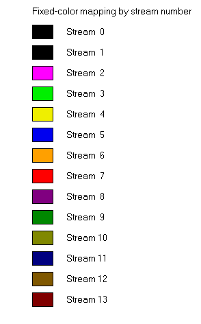
EEGer has both “feedback modes” and “reward modes”. “Feedback modes” describe (control) the signal routing and processing of inputs, displays, and (game) outputs. Various modes are available depending on the specific layout (screen configuration). Details on all modes can be found in the Technical Manual.
Commonly available feedback modes:
SingleA - Input data comes from channel A; reward is SMR reward
SingleB - Input data comes from channel B; reward is SMR reward
Sum - Input data is sum of A and B; reward is SMR reward
Differ - Input is A lowpass value minus B lowpass value; reward is SMR reward
Psync - Input is A & B lowpass/bandpass values; reward is SMR reward
Async - Input is A & B lowpass/bandpass values; reward is SMR reward
GAsync - Input is A & B lowpass values; reward is SMR reward
AminusB - Input is A & B lowpass/bandpass values; reward is SMR reward
BminusA - Input is A & B lowpass/bandpass values; reward is SMR reward
PDelta - Input is A & B lowpass/bandpass values; reward is time-sample deviation
of phase difference between A & B
RatioA - Input is A; reward is ratio of reward trace to inhibit trace just above reward trace
RatioB - Input is B; reward is ratio of reward trace to inhibit trace just above reward trace
RatioAB - Input is A & B; reward is ratio of A amplitude to B amplitude.
RatioBA - Input is A & B; reward is ratio of B amplitude to A amplitude.
D/S-Ratio - Input is A & B; reward is ratio of (A-B) amplitudes to (A+B) amplitudes
Unity - Input is A & B; reward is1- ratio of
absolute value (A-B) amplitudes
to (A+B) amplitudes
Dual - Input is A & B lowpass values (A feeds 3 traces, B feeds 3 traces);
reward is SMR
MonitorA - Input is A lowpass value; No rewards or game outputs
MonitorAB - Input is A & B lowpass values; 6 traces from A, and 6 from B;
No rewards or game outputs
MonitorB - Input is B lowpass value; No rewards or game outputs
If the zscore option is available, additional reward modes are possible. See the zscore appendix (Appendix 12) for a discussion of these modes
There are approximately 200 modes.
Available reward modes (assuming there ARE some reward outputs):
Rwrd - Reward condition is integral value at or above target threshold.
Down - Reward condition is integral value at or below target threshold.
Cntr - Reward condition is when difference between current value and average value is less than target threshold.
Elev - Same as Rwrd but game output value is limited to threshold value.
DevU - Deviation is absolute difference between average and instantaneous integral. Reward is when this smoothed value is at or above target threshold.
DevD - Deviation is absolute difference between average and instantaneous integral. Reward is when this smoothed value is at or below target threshold.
Band - Reward condition is signal value within offsets from threshold setting. Limits are set using the Band Control popup.
This appendix describes the kinds of sound controls EEGer allows with the EEGer Game Set (EGS)games. Third party games in general do NOT support these modes, which are set during the Game Initialization or tailoring phases.
There are three categories of sounds: discrete rewards, strand-related sounds, and special.
Discrete reward sounds are generated whenever the therapist computer issues a “reward” command. These sounds are intended to be short (shorter than the reward interval!) and indicate a successful “state” to the client. The games have two reward sound possibilities: “Reward” and “Success”. The “Success” sound is only used for those games that have some success criteria associated (completing a maze, filling a picture, reaching the end of the jumpbox display). Discrete reward sounds have controls for which channels the sound is played through. Normally BOTH is the selection. It is possible to select either LEFT or RIGHT also. The ALTERNATE selection alternates between LEFT and RIGHT for the number of seconds specified as the limit, then defaults to BOTH. Again, the reward sound is only generated when triggered by the therapist computer. Certain games respond to spike-triggered sounds as specified in the tailoring files.
Strand-related sounds are associated with particular processing bands and generally relate to amplitudes, ratios, etc., of the data in those bands. There are six separate sound possibilities defined although you can only use as many sounds as are driven by the therapist computer (which in turn is controlled by the current layout). All six sound options work identically (using the individual options, of course). It is possible to select BOTH, LEFT, or RIGHT channel for the sound output. The mode of operation for the sound is one of the following:
|
CONTINUOUS |
The sound plays during feedback |
|
ENABLED |
The sound plays during feedback but ONLY if all inhibits are below threshold and all rewards are at or above threshold. |
|
NOTENABLED |
The sound plays during feedback but if any inhibits is above threshold or any rewards is below threshold. |
|
PROPORTIONAL |
The sound plays during feedback and the volume is proportional to the ratio of amplitude and threshold. The higher the signal is over threshold, the louder it is. |
|
ENABLEDPROP |
A combination of ENABLED and PROPORTIONAL |
|
OVER |
The sound plays during feedback only if the amplitude is over the threshold |
|
UNDER |
The sound plays during feedback only if the amplitude is under the threshold. |
The clinician must select which game strand drives each sound. Each layout and feedback mode has a discrete mapping of stream/trace to strand. The commonly-used tables are as follows:
Layout: 5
|
Trace |
Strand |
|---|---|
|
2 |
0 |
|
3 |
1 or 2 |
|
4 |
3 |
Layout: 6,inhibit
|
Trace |
Strand |
|---|---|
|
2 |
0 |
|
3 |
4 |
|
4 |
1 or 2 |
|
5 |
3 |
Layout: 6,reward
|
Trace |
Strand |
|---|---|
|
2 |
0 |
|
3 |
1 or 2 |
|
4 |
5 or 6 |
|
5 |
3 |
Layout: 8
|
Trace |
Strand |
|---|---|
|
2 |
0 |
|
3 |
1 or 2 |
|
4 |
3 |
|
5 |
4 |
|
6 |
5 or 6 |
|
7 |
7 |
The complete set of mappings is contained in the Technical Manual.
Special sounds are those unrelated to specific strands. The only category of these are those sounds controlled by the overall reward %. A separate tailored value is the RWVALUES variable with contains 6 (comma-delineated) percentage values. Modes used with these settings are:
|
RWOVERn |
The sound plays only when the overall reward % is greater than or equal the nth percentage specified in the RWVALUES setting. |
|
RWUNDERn |
The sound plays only when the overall reward % is less than the nth percentage specified in the RWVALUES setting. |
The EEGer Input-Output test program was designed to test the interface between the amplifier/encoder devices supported by EEGer. It uses the identical interface software used by the realtime processing but with no filtering or user adjustments. A typical screen looks like this:
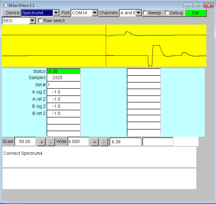
The EIOTEST program automatically decodes the current EEGer options set on the configuration pages as the startup settings. Changes made during the EIOTEST program do NOT alter the EEGer configuration settings. Error information or successful connection information is shown in the bottom boxes. The yellow area is an updated display of the raw data from the device. The columns of numbers mean different things for each device. In general, numbers changing in the right-hand column mean bad things. The top left value in the middle blue area represents the status of the device. Green means everything is OK. Yellow or red means errors in communication or device data. This field is the same value as displayed in the status bar at the bottom during live sessions. Values on the left are informational. Values with pink backgrounds are error counters/values. The Scale setting controls the scale value for the yellow display. The Wide setting control how many seconds wide the display represents.
On the top rows are selection options.
Device – this allows selecting a different device for testing
Port – this allows selection of serial port for testing for those devices requiring a serial port. Only ports COM1 through COM16 are allowed and only initially-detected ports are active. Undetected ports at EIOTEST startup are inactive (grayed out).
Channels – selects which raw data channels will be displayed.
Sweep – Selects if swept or scrolling display mode is to be used.
Debug enables display of the debug information for the device (as shown on the realtime debug display).
Exit – exits the IOTEST program. The ESC key also exits the program.
The next row of options controls other settings. This row is different for every different kind of amplifier/encoder. The option showing EEG is actually an option selector that allows other operations on devices capable of them. The other choices are Impedance and Calibration.
The ProComp2 checkbox allows changing the commanded mode between ProComp2 and other Thought Technology devices since the TT software cannot inherently detect a ProComp2 (so the battery voltage is correctly displayed).
The Biograph or Spectrum checkbox allows switching between Thought Technology interface modes. Spectrum is the default mode for ProSB interfaced devices while Biograph is required for TTUSB interfaced devices. This setting must match the switch settings in the device.
Bypass is an internal test mode.
Raw select determines if J&J devices use the standard filtered input or the unfiltered raw input.
A/D Base controls which A/D card number is used.
24-bit mode selects 24-bit instead of 16-bit mode on Atlantis devices.
Link refs links references internally to the amplifier/encoder.
Max value sets the maximum scale value for the esiPro/A200/A400 devices.
4-channel forces Wiz devices in 4-channel mode.
Turn off electrode monitoring disables Wiz monitoring of electrode status
For ProComp testing, the columns of numbers assist in divining the current device settings.
Here is an example of the IO test reporting some failures:
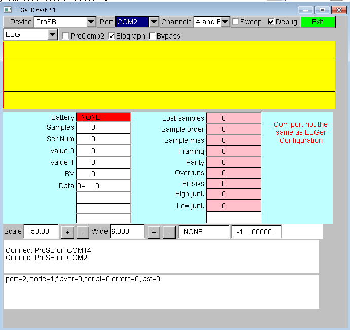
Numbers changing in the pink boxes and lack of updates to the yellow data indicate a settings issue.
If no numbers were changing and no connect error was reported, this would indicate some communication error between the device and the computer - usually a fiber connection or battery problem.
In any event, error messages at the bottom of the screen mean that the software was unable to communicate with the device. Please contact Technical Support for assistance in resolving the issue.
The game initialization tool is the tool which searches the user computer for the special files which identify a “game definition”. A list of all the games discovered is then presented to the user for establishment of “option possibilities”. By this, I mean the set of sound/picture/video files which the therapist will (later) be able to select from.
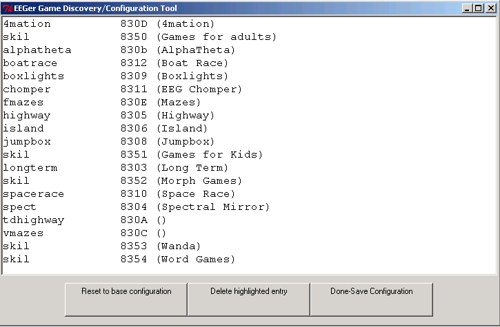
The “Reset to base configuration” button removes any user selections and reverts the definitions to the delivered base settings. Clicking this loses any user file/directory settings that may have been made.
The “Delete highlighted entry” button removes the currently highlighted game from showing on the game selection screen (and from use).
Double-clicking on a game line will give the specifics of each game definition.
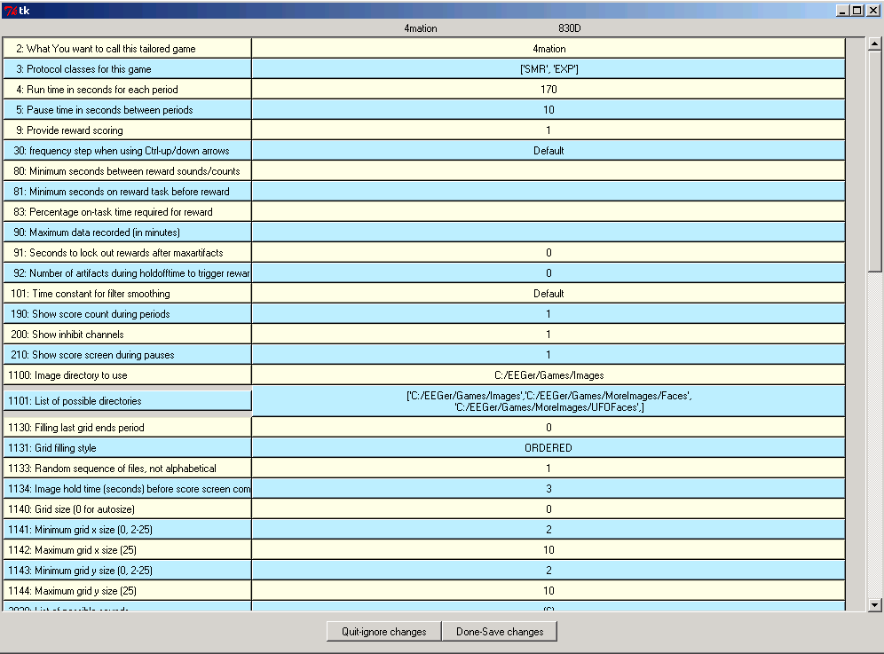
The user can add additional sounds, etc. to each definition using various browse/selection menus.
Selecting Done-Save Changes saves the specified selections for that game. Selecting Done-Save Configuration at the top menu saves ALL the game specifications for later transmittal to the therapist computer. The user can entirely delete games from ever being a choice on the therapist computer (until the next memory scan). During therapist setup, the saved specifications are sent to the therapist machine for “tailoring”.
Support for Applied Neuroscience, Inc. (ANI) Z Score training is available in EEGer version 4.3 and later. These instructions provide directions to set up and activate the Z Scores feature in EEGer.
For Z Scores to function in EEGer, the following items must be valid:
ANI biofeedback software must be installed by the EEGer installer in the EEGer-specified location.
A valid EEGer license for Z Scores must be installed.
A valid ANI passkey must be installed.
A valid birth date must be entered for the client prior to training (since the ANI software needs client age).
Valid site(s) and frequency ranges must be entered in the client’s session plan prior to training.
Install EEGer4 software
EEGer version 4.3 and subsequent program updates are available on CD from EEG Store or can be downloaded from the EEGer website: support.eeger.com. Follow instructions provided with the CD or on the website to install.
Be sure to check the option to INSTALL THE ANI ZSCORE FILES on the Select Additional Tasks display during the installation process.
Install the EEGer Keyblock File:
Insert the EEGer Keyblock File CD in your CD/DVD drive.
If the contents of the CD are displayed automatically, close the window. You must load the key using EEGer.
Start the EEGer program. From the Files menu, select Read EEGer Keyblock Files.
Select the CD/DVD drive for the Look In field.
The updated keyfile is displayed on the Open dialog. Click the filename to select/highlight and click Open.
Obtain the Z Score Security Key from ANI
Start the EEGer program, if necessary.
From the Options menu, select Create ANI Biofeedback 2-Channel Key or Create ANI Biofeedback 4-Channel Key. Accept the License agreement and the key screen appears:
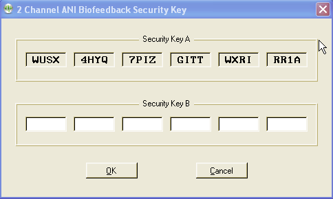
Contact ANI.
Email Security Code A as it displays on your EEGer screen to qeeg@appliedneuroscience.com and cc: rwthatcher@yahoo.com (If you do not have access to email, please call EEG Store for assistance at 888-521-9803)
Repeat steps 1 and 2 to enter the code they provide for Security Key B. Click OK to activate the new feature.
Applied Neuroscience, Inc. /
228 176th Terrace Drive / St. Petersburg, FL
33708
PHONE: (727)244-0240 /
FAX: (727) 319-1027 / EMAIL:
qeeg@appliedneuroscience.com
NOTE: The ANI Z Score Security Key is computer specific. If you install EEGer on another computer or have to recover after hard drive failure, you must contact ANI to obtain a new Security Key.
EEGer REWARD MODES FOR Z SCORES
In Plan Session, for the Z Score Setup stage, click the Feedback button to choose the desired mode. The mode can also be changed on the EEG training display by pressing Shift+F3 to select a different reward mode.
ZComposite - reward is some combination of computed data as set during the options settings.
ZAsymm - reward is standard deviation of absolute asymmetry for designated frequency band (2 channels)
ZCohere - reward is standard deviation of coherence for designated frequency band (2 channels)
ZPhase - reward is standard deviation of absolute phase for designated frequency ban (2 channels)
ZAbsPwrA - reward is standard deviation of absolute power from A site for designated frequency band
ZAbsPwrB - reward is standard deviation of absolute power from B site for designated frequency band
ZRelPwrA - reward is standard deviation of relative power from A site for designated frequency band
ZRelPwrB - reward is standard deviation of relative power from B site for designated frequency band
ZPRatioA - reward is standard deviation of power rations from A site for designated frequency band
ZPRatioB - reward is standard deviation of power rations from B site for designated frequency band
NOTE: For Z Score training, enter a second training site (Input ChB) even if using a single-channel feedback mode. If only one site is entered, a “site error” may appear on the EEG training or replay screen. EEGer checks for a valid two-channel setup in case of a change to a two-channel mode while on the EEG training display.
NOTE: For 4-channel setups, channels C and D are also available.
EEGer automatically adjusts frequency bands when entering/exiting a Z Score feedback mode to match the closest standardized Z Score band.
|
Frequency bands |
Enter this Reward Frequency Range in EEGer Plan Session (Hz) |
|
Power Ratios |
Enter this Reward Frequency Range in EEGer Plan Session (Hz) |
|
Delta |
1.0 - 4.0 |
|
Delta / Theta |
1.0 - 4.0 |
|
Theta |
4.0 - 8.0 |
|
Delta / Alpha |
4.0 - 8.0 |
|
Alpha |
8.0 - 12.0 |
|
Delta / Beta |
8.0 - 12.0 |
|
Beta |
12.0 - 25.0 |
|
Delta / High Beta |
12.0 - 25.0 |
|
High Beta |
25.0 - 30.0 |
|
Theta / Alpha |
25.0 - 30.0 |
|
Beta 1 |
12.0 -15.0 |
|
Theta / Beta |
12.0 -15.0 |
|
Beta 2 |
15.0 - 18.0 |
|
Theta / High Beta |
15.0 - 18.0 |
|
Beta 3 |
18.0 - 25.0 |
|
Alpha / Beta |
18.0 - 25.0 |
|
|
|
|
Alpha / High Beta |
35.0 - 37.0 |
|
|
|
|
Beta / High Beta |
37.0 - 39.0 |
Valid sites:
FP1
FP2
F3
F4
F7
F8
Fz
C3
C4
Cz
P3
P4
O1
O2
T3
T4
T5
T6
Pz
Review Options:
EEGer Review includes additional options for viewing data from sessions recorded using a Z Score reward mode.
Files can be exported in EDF+ format for analysis in ANI’s NeuroGuide or other software that can import EDF+ format.
Site and Frequency Settings: When a Z Score feedback mode is selected for training, EEGer checks the selected site(s) and frequency against the available Z Score options. A message is displayed for invalid site(s). There must be two channels of EEG data for some of the options. For frequency, the Reward band is adjusted to the closest valid Z Score range.
Feedback Mode: To change the feedback mode, press Shift+F3. Use the arrow keys to move to the desired mode and press + to activate. EEGer must confirm the sites and frequency again if a Z Score mode is selected.
EEGer contains a primitive text editor to allow notes and observations to be recorded during a feedback session (live or replay), client data review, and spectral data review. A typical screen looks like this:
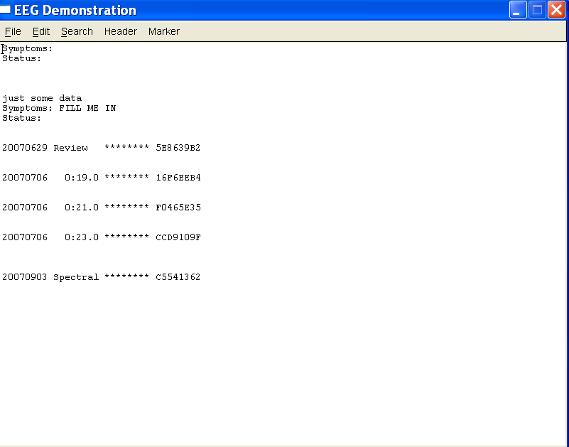
The client “name” is shown on the top line (subject to HIPAA settings). The “Header” button pastes in the boilerplate file (specified by editing it from the “Preferences” menu) at the current cursor location. The “Marker” button pastes in a line of text with the date/time information. Also on the marker line is the relative session time (for live/replay sessions) or “Review” or “Spectral” to show when the marker was inserted. The remaining information (those letters/numbers on the marker line) are encoded information as to when the marker was “actually” created so that annotations can be forensically determined. However, the marker and header data is just text and can be deleted like any other text.
The editor is commonly started using F8 from wherever possible. It can be closed (and data saved) using F8, File->Exit, or clicking on the “x” in the upper right corner. The data is ALWAYS saved when the editor is closed. It is not possible to abort saving the data.
All tailoring options have a unique number (prefix). Each unique number refers to a specific function which is common to all games which have that option. Not every option is present or available for every game.
2: What You want to call this tailored game
This is the text that appears on the Therapist selection screen and NOT what appears on the client Game Menu.
3: Protocol classes for this game
Selects which protocol classes this game is available for. Usually SMR and EXP since there is only one Alpha-Theta game.
4: Run time in seconds for each period
The length of each run period. Note that mazes and 4mation (among others) have the option to terminate a period when the 'game' completes. Default is 170 seconds.
5: Pause time in seconds between periods
This is the rest time between run periods. Default is 10 seconds.
9: Provide reward scoring
This option allows reward scoring (beeps) to occur.
30: Frequency step when using Ctrl-up/down arrows
Selects the frequency step size when changing reward frequencies. Note that this only works if you have selected a filter set in the Setup settings that supports the step size.
80: Minimum seconds between reward sounds/counts
Sets the minimum time between possible reward counts/beeps.
81: Minimum seconds on reward task before reward
Sets the minimum time that a rewardable state must be maintained before a reward/beep is commanded. Setting this too long will make rewarding very difficult since the measure is CONTINUOUS rewardable state. This action can be turned on/off during a session using the Ctrl-F2 option.
83: Percentage on-task time required for reward
Sets the minimum overall reward percentage to be maintained before a reward/beep is commanded. This action can be turned on/off during a session using the Ctrl-F2 option.
90: Maximum data recorded (in minutes)
Specifies how much storage is reserved for a session. Only this much data will be recorded. The maximum time is 90 minutes for a session. This time starts when the realtime session begins and ends when the realtime session exits.
91: Seconds to lock out rewards after maxartifacts
This specifies how long to monitor for artifacts and how long to inhibit rewards when the artifact count is exceeded. Intended to keep clients from artificially increasing the number of points scored by deliberately causing artifacts.
92: Number of artifacts during holdofftime to trigger reward lockout
Sets how many artifacts during the above specified time triggers the artifact reward inhibit.
101: Time constant for filter smoothing
Selects filter smoothing time constant. Usually 0.5 seconds. Larger values slow down reward/inhibit responses.
190: Show score count during periods
Display/not display the score count DURING a period.
200: Show inhibit channels
Display/not display inhibit data (if game supports this). In any case, no inhibit data will be sent anyway to the game is this is set to 0.
210: Show score screen during pauses
Show/not show score screen during pauses.
1050: Show reward gauges at bottom
1051: Show inhibit gauges at bottom
1052: Show monitor gauges at bottom
1080: Colorset to use for game frequency-specific colors
Specify which user-configured color set to use. Only spectral mirror and long-term displays use this at the current time.
1090: Mode used for spike detection
One of the spike detector modes. Available modes are:
Disabled
In Period - display on therapist display, sound triggered on game if in feedback
Always - display on therapist display, sound triggered on game at any time
Just Show - display on therapist display
1091: Seconds to wait after spike to see if its
really artifact
How long to wait after spike to see if its really an artifact.
1100: Image directory to use
Specify which image directory to get pictures from.
1101: List of possible directories
(Game Initialization Tool) Selection of possible directories to use at tailoring time.
1130: Filling last grid ends period
Option to end a period when the grid/picture/maze completes.
1131: Grid filling style
Select grid fill mode – Ordered (left to right, top to bottom), Random, Weighted (random first grid selection then fill adjoining grids).
1133: Random sequence of files, not alphabetical
Specify random ordering of files.
1134: Image hold time (seconds) before score screen comes up
Specify how long a completed image is displayed before (possible) score screen appears.
1140: Grid size (0 for autosize)
A non-zero value forces a MxM rectangular grid for every image. Zero value picks random width/height sizes between specified limits below.
1141: Minimum grid x size (0, 2-25)
1142: Maximum grid x size (25)
1143: Minimum grid y size (0, 2-25)
1144: Maximum grid y size (25)
1145: Show first element of reveal at beginning
(dkgames) Shows first piece of a grid before the first reward.
1146: Show game rule conditions
(dkgames) Displays rule conditions during menu display.
1150: Seconds needed to remain on task
(Jumpbox) Maximum seconds allowed between rewards to keep chip moving.
1164: Swap alpha and theta sounds
(Alpha-Theta) Swaps water/ocean sounds.
1165: Transition rate for alpha/theta state change
(Alpha-Theta) Selects transition rate for state change. This can also be changed during A-T sessions using the volume control popup.
1166: Option to use highest reward percentage instead of Theta bias
(Alpha-Theta) Use highest reward percentage to choose reward sound rather than Theta if both bands are in rewardable state.
1167: Optional transition percentage from edge for faster transition rate
(Alpha-Theta) Allows selection of faster (doubled) change rate when within selected percentage of either extreme of alpha or theta state.
1170: 1 for classic game appearance, 0 otherwise
(Boxlights, Jumpbox, Highway, Island)
1171: 1 for warm, 2 for cold, 0 for color dependency
(Boxlights, Jumpbox, Highway, Island)
1172: 1 for frog image instead of boring black bars
(Jumpbox)
1173: Number of peripheral thermometers to display
(Jumpbox, Boxlights, Highway, Island)
1180: Use random point for iris center
(Iris) Use random point for Iris center instead of screen center.
1181: Color to use for reward 1
(Iris) Select color of mask to use for first reward.
1182: Color to use for reward 2
(Iris) Select color of mask to use for second reward.
1183: Color to use for reward 3
(Iris) Select color of mask to use for third reward.
1184: Color to use for reward 4
(Iris) Select color of mask to use for fourth reward.
1190: Use a fixed color background instead of pictures
(Iris)
1191: Select color of fixed background
(Iris)
1200: Timer for expected reward rate
(dkgames) Seconds allowed between rewards before previous image pieces are UNdisplayed. This action can be toggled on/off during a session using the S popup menu.
1302: Starting maze index
(Mazes)
1303: Use mazes in random order instead of sequential
(Mazes)
1402: Draw longterm display lines double-high
(longterm)
1403: Time width of long-term window
(longterm)
1410: Smoothing factor
(longterm,Iris) Smoothing factor for data changes
1411: Scale factor for
Iris
(Iris) Controls relative sizing of iris.
1700: Which artwork to use as overlay (0-3)
(DVDGame) Which overlay image to use for overlay mode.
1701: What kind of video control to use
(DVDGame) Options are OVERLAY, BLUR, BLACK, WHITE
1702: Time (seconds) to go from worst to best video
(DVDGame) How long to transition from complete obscuration to completely clear video when in a rewardable state.
1703: Time (seconds) to go from best to worst video
(DVDGame) How long to transition from completely clear to completely obscured when NOT in a rewardable state.
1704: Minimum worst video percentage
(DVDGame) Worst obscuration percentage (video will never be obscured more than this percentage).
1706: Percentage of border size
(DVDGame) (not currently used)
1707: Pause video during pause
(DVDGame) Pause DVD playback when ever in PAUSE or STAGE state.
1708: Enable feedback sounds in addition to DVD soundtrack
(DVDGame) Provide normal EEGer sound feedback in addition to DVD sound. This includes reward sounds as well as all the other sound modes.
1709: Action to take if DVD is not playing (time running)
Decide to pause/not pause feedback if DVD reports not running.
2020: List of possible sounds
(Game Initialization Tool) List of possible sound files to select during tailoring.
2021: Pathname of reward sound
Full path of selected reward sound.
2023: Which L/R speaker the reward sound comes from
Sounds can come from the Left/Right/Both/Alternating speakers.
2024: Pathname of success sound
Full path of success sound for games which have a “success” condition.
2025: Which L/R speaker the success sound comes from
Sounds can come from the Left/Right/Both speakers.
2026: Maximum seconds for alternating reward sounds
If Alternating sounds was selected, specifies how many seconds from beginning of period that the alternation continues. After that time, sounds come from Both speakers.
2029: Sound channel for spike sound
Sound channel number for spike sound.
2030: Pathname of sound 3
Full pathname of a sound file
2031: Sound 3 play mode
Sound play modes are described in the Sound Controls appendix of the documentation.
2032: Which L/R speaker sound 3 comes from
Sounds can come from the Left/Right/Both speakers.
2033: Which strand feeds sound 3
Specifies which data path controls the sound action. This is described in the Technical Manual.
2034: Pathname of sound 4
2035: Sound 4 play mode
2036: Which L/R speaker sound 4 comes from
2037: Which strand feeds sound 4
2038: Pathname of sound 5
2039: Sound 5 play mode
2040: Which L/R speaker sound 5 comes from
2041: Which strand feeds sound 5
2042: Pathname of sound 6
2043: Sound 6 play mode
2044: Which L/R speaker sound 6 comes from
2045: Which strand feeds sound 6
2046: Pathname of sound 7
2047: Sound 7 play mode
2048: Which L/R speaker sound 7 comes from
2049: Which strand feeds sound 7
2050: Pathname of sound 8
2051: Sound 8 play mode
2052: Which L/R speaker sound 8 comes from
2053: Which strand feeds sound 8
2060: 6 comma-separated overall percentage enable
points
2160: Sound file for alpha reward
Pathname of Alpha-Theta alpha reward (high-pitched bell)
2161: Sound file for theta reward
Pathname of A-T theta reward (low-pitched gong)
2162: Sound file for alpha state
Pathname of A-T alpha state (running stream)
2163: Sound file for theta state
Pathname of A-T theta state (ocean waves)
3000: Maximum number of strands to use
Reserved
3001: Maximum number of inhibit channels to use
Reserved
3002: Maximum number of reward channels to use
Reserved
3003: Maximum number of sounds to use
Reserved
4888: (GTOOL ONLY) Game name title order
Controls display order on the Client game menu
These instructions provide directions to activate and configure Coherence training modes.
For Coherence training, the following items must be valid:
• A valid EEGer license for Coherence training must be installed.
• All modes use two channels: Channel A and B or C and D; 2 signal, 2 reference and either 1 shared ground or 2 ground electrodes (dependent upon amplifier model). ProComp/Infiniti amplifiers: An additional part, the FlexPro pre-amplifier, is necessary to utilize Channel B.
Note: All recent versions of EEGer support the coherence modes automatically. If using some early version that does NOT have coherence enabled, please contact Customer Support for the enabling keyblock.
A. Select a Coherence training mode in Plan Session
Select Client for Coherence training.
Click Choose Layout to choose the number of traces for the EEG display, except 8-trace Layout (Dual mode training layout).
Click Plan Session.
In the Setup stage, enter the sites for Input Chan A and Input Chan B.
Click Feedback Mode at the top of the middle column to display a menu of options. Click the appropriate button to select the Coherence mode:
Psync Comparison between filtered A and B envelopes (formerly Synchrony)
Async Comparison between filtered A and B envelope slopes (formerly Comodulation)
GAsync Comparison between lowpass A and B envelope slopes (formerly Global Comodulation)
AminusB Difference between filtered A and B envelopes
BminusA Difference between filtered B and A envelopes
PDelta Comparison of phase difference between A and B signals
D/S-Ratio Ratio of (A-B) to (A+B)
Unity Compute 1-|(A-B)|/(A+B) similar to D/S ratio except absolute value
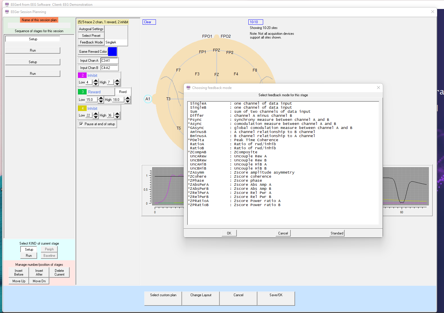
Enter other relevant details for Setup and Run stages and click OK when finished.
B. Begin Session
Apply sensors to the appropriate sites and connect to ChA and ChB of the amplifier.
Set scales and thresholds and press F5 to run the session.
To change the Coherence training mode during training, press Shift+F3 for a menu of choices.
It is suggested that you make changes to the session plan prior to the arrival of your client.
SET UP A COHERENCE TRAINING SESSION
Once EEGer is launched, select your client and go to the Plan Session screen.
Click Feedback Mode. You should get a long vertical list of choices.
Choose Psync. Make sure that Psync is what now displays in the box directly next to the Feedback Mode box.
Coherence training requires input from 2 channels so make sure that you set up both Channel A and Channel B on your amplifier. While on the Plan Session screen enter the site in the Input Chan A box (for example C4-A2) and the site in the Input Chan B box (for example C3-A1). These sites should be derived from a qEEG report.
Using the bandwidth information provided in the qEEG report; enter the numeric values for the frequencies that need coherence training in the REWARD band (for example "increase coherence in the 8-11 Hz range").
Click the button labeled Reward to select the appropriate mode for the type of coherence training to be performed. If you wish to INCREASE coherence, choose Rwrd. If you wish to DECREASE coherence, select Down and the box next to the REWARD box changes to Down.
NOTE: Coherence training is performed using the REWARD frequency band(s). Any Inhibit bands in the selected layout can be set to values based on your training or according to information in the QEEG report. The inhibit frequencies may overlap the reward/coherence frequencies to any degree.
Set the RUN time for the length of time you wish to do coherence training.
RUN A COHERENCE TRAINING SESSION
Go to Begin Session and select a game.
At the bottom of the Therapist screen you should see the word Psync. This confirms that you set up the training mode correctly and are properly licensed to run coherence training.
Press the Page Down key until you highlight the Reward band.
Once the Reward band is highlighted press F9; the Scale number in the Reward band should now be highlighted.
Use the – or + keys to change the scale to 2. Press Enter twice to de-select.
NOTES:
While running a coherence session, the signal in the Reward band does not look like a typical EEG signal, it is a smoother line that goes UP when the two signals (Channel A and Channel B) are MORE coherent and DOWN when they are LESS coherent. The number next to the AVG under the Reward band now represents the numerical value of coherence, not amplitude. Perfect coherence shows as 10. (While increased coherence may be the goal, perfect coherence is not necessarily ideal for achieving optimal performance.)
Typically you can set the % Above numbers in the Reward band (now functioning as the coherence band) at 70%-80% to provide adequate information about the level of coherence. Set the inhibit band % Above numbers based on previous sessions or in a way that gives enough information about the frequency you are choosing. (This is a clinical judgment issue.)
Instructions prepared and reviewed by Joy Lunt, R.N., BCIA-EEG Fellow; Harold Burke, Ph.D., BCIAC; Gary Schummer, Ph.D.
Purpose of the utility
This utility program exists to allow transfer of EEGer Session Plans and Presets between clients and between clinicians.
Session plans are comprised of a series of setup stages (setting frequencies, electrode sites, modes, etc.) and run stages (time to run at the previous setup).
Presets are comprised of single setup stages that can be entered into a session plan from a selection menu. They have all the same settings/values that a setup stage in a session plan can have and are intended to speed up creating custom session plans for a client. Presets are organized by protocol class and by layout.
Session plans can be packaged (by the utility) into tiny compressed files (ELS files). These files can then be (re)loaded as either default session plans or session plans for specific clients. They can also be transmitted via email or downloaded (using Home-use utility) and installed on any clinician's system (and then installed wherever). The limitation is that the plans are “Layout-specific” meaning that you cannot load a 5-trace layout plan into a 6-trace layout (but even if selected incorrectly, the EEGer will handle that internally).
Presets can be gathered up and packaged (by the utility) into tiny compressed files (ELP files). The presets can then be added to existing presets, either for the same protocol class or for a related class (AT presets NOT allowed in SMR, for example). They can also be transmitted via email or downloaded (Home-use utility) and installed on any clinician's system (and then installed wherever).
Installation
The Protocol Transfer utility is already preinstalled along with EEGer. Also, the utility is available from our website (Click on the Downloadable Files in the download page).
The utility is installed just like other installation programs – start it and acknowledge the prompts. The only option during installation is whether or not a desktop icon is created for the utility.
Starting the utility
On the main EEGer screen, navigate to Utilities menu and select ‘save/install protocol sets (session plans and presets)’. Additionally, the utility can also be opened by navigating to on Start menu->All Programs->EEGer->Protocol Transfer Utility or Double click on the desktop icon.
Usage
There are six option buttons on the main screen:
Create Installable Session Plan from Existing Client
Install Session Plan
Create Installable Presets from Existing Presets
Install Presets (you must select protocol class)
Although the options are self-explanatory, detailed procedures are described following.
The main menu looks like this:
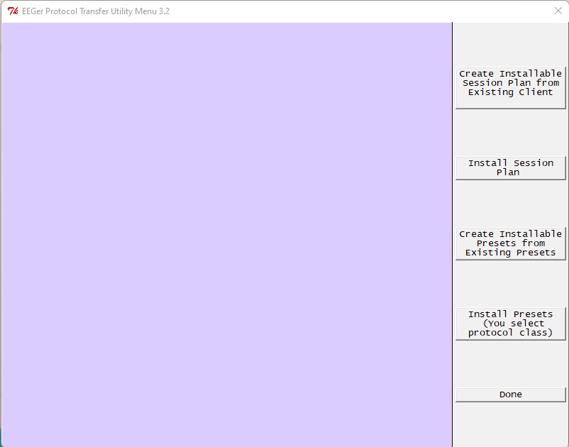
This option us selected to createinstallable session plan to use.up a client selection screen just like in EEGer:
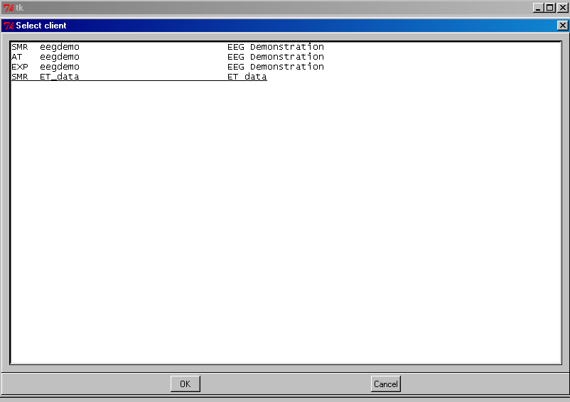
At this point select the client/protocol class you want to draw a session plan from. The next screen
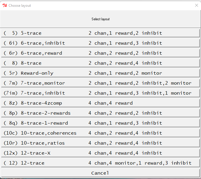
lets you select which layout the session plan is drawn from. The plan itself is unmodified – only a copy is made. Then, you enter a descriptive line (such as why this is a great session plan):
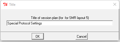
Now you select a file name for the file (which should help in selecting such a file later):
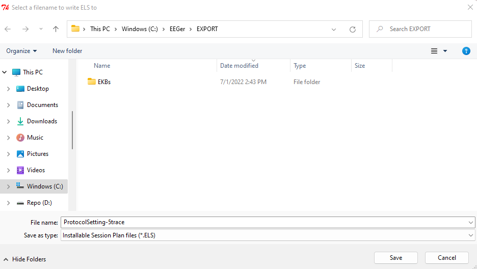
The default location for these files is C:\EEGer\Export but you can save them anywhere you like.
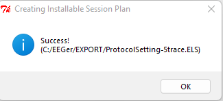
Next -
Now that we have an installable session plan, let's install it.
Clicking on “Install Session Plan” brings up a file selection menu:
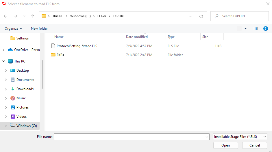
Selecting (double click or select and click on Open) a file lets the utility validate that it IS a valid session plan and prompts the title of the session plan previously configured while creating ELS file.
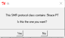
Select ‘yes’ if the title of the session plan is what you need to install. Another prompt now displays the two options by which session plan can be installed. By selecting ‘Custom plan pool’ the session plan can be selected/configured to any client (for a same layout) in the plan session screen and by selecting ‘Specific client’ the session plan can be saved as the default session plan only to a specific client.
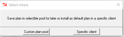
When the option of saving the session plan to a specific client is selected, a client selection dialog box is brought up. A specific client that will inherit the session plan must be selected.
Once the session plan is
saved, EEGer closes the utility and EEGer main screen is back
up
This option is useful if you want to install a session plan as a selectable custom session plan in EEGer.
The custom sessionplan is protocol class specific and hence, the utility display the options.
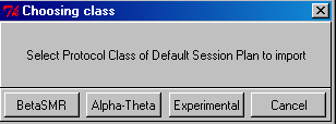
Another dialog box with option of naming your custom session is displayed. You can either leave the parent title or enter a new session plan title.
By selecting ‘Use this title’, users can select this session plan (picked up from ELS) by selecting custom session plan button on the plan session screen. By selecting ‘Default’, the session plan in the ELS file becomes the default session plan in EEGer for the protocol class selected.
To create an installable presets file, click on “Create Installable Presets from Existing Presets” from the main menu.
Then choose the protocol class to export from.
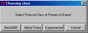
You then get a list of the layouts for that protocol class:
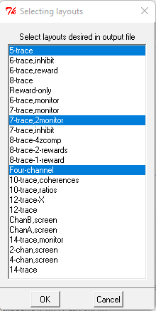
You can select one or more
of the layouts to export presets from (Ctrl-click for more than
one).
When done selecting layouts, click OK and the following screen comes up:
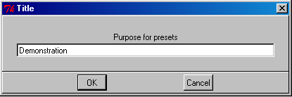
Enter something useful as a reminder.
Clicking on OK brings us to the export file naming screen:
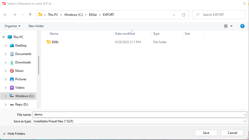
It is usually better to pick a (short) descriptive file name so you can recognize it later.
Then, of course:
To actually install presets, click on “Install Presets” from the main menu. A file locator screen appears:
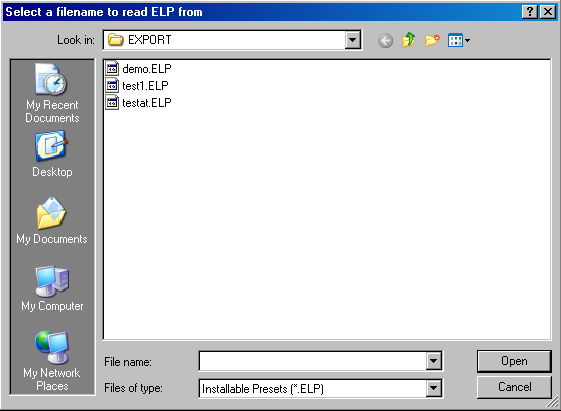
After selecting a presets file, the following choices are available:
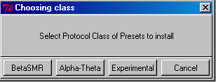
Normally, you will then get:
You may also get:
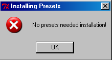
This means you had all the presets in the file already existent in your presets for that protocol class.
The Remote Flash Utility is a tool to allow remote re-creation of a Remote User flash drive. It is intended for rare occasions where a remote client flash drive has become corrupt and cannot be used. The normal case if for clients to return flash drives to clinicians so they can review and properly evaluate the treatment protocol. However, the client is sometimes too far away to make the extra trip for a new flash drive.
Basically, the tool works as follows:
The Therapist creates a remote user flash drive just as always done (onto a flash drive in the Therapist's office).
The Therapist starts the Remote Flash Utility and the following screen comes up:
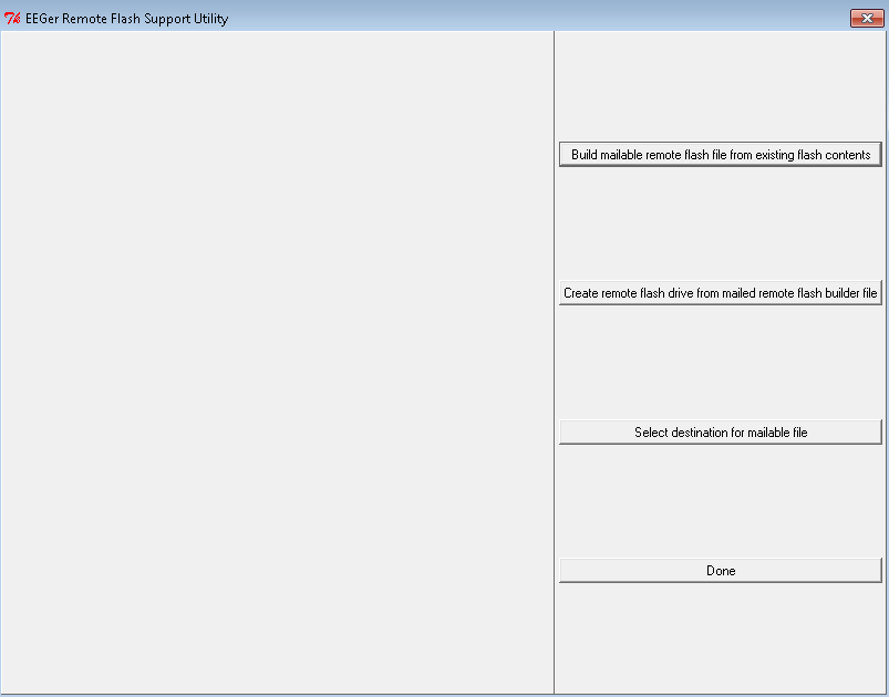
The Therapist selects the top option (“Build mailable remote flash file from existing flash contents”).
The Therapist is prompted to select the flash drive just created:
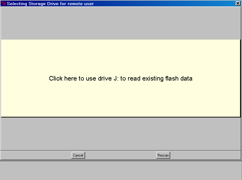
The utility builds an email-suitable file and places it on the desktop:
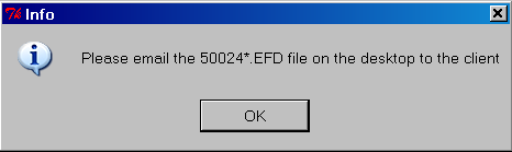
Note: some versions of Windows or Windows-logons will not permit writing the file to the desktop.
In that case, used the option “Select destination for mailable file” from the menu options (first) and select some other option.
The filename of the file is the dongle number (of the destination dongle), some letters, and the extension .EFD (meaning something like EEGer Flash Drive).
The Therapist emails the .EFD file to the eagerly waiting client.
When the client receives the email, it must be copied to the client's therapist computer. That file must remain readable while installing the contents onto a flash drive. It is possible to copy the EFD file onto the DESTINATION flash drive.
The client starts the Remote Flash Utility and sees the main screen:
The client selects the middle button (“Create remote flash drive from mailed flash builder file”).
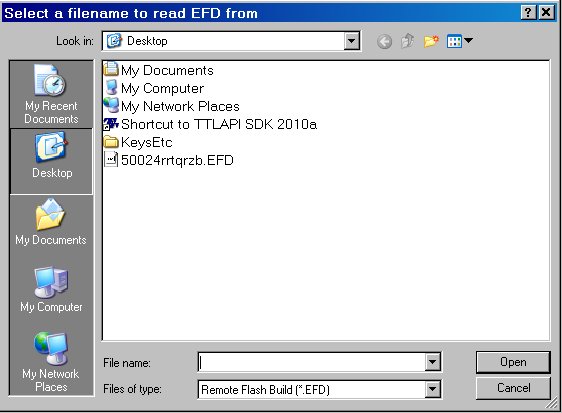
The client is then prompted to select the mailed (.EFD) file:
After verifying that the file is a valid remote flash file, the client is prompted to select the destination flash drive:
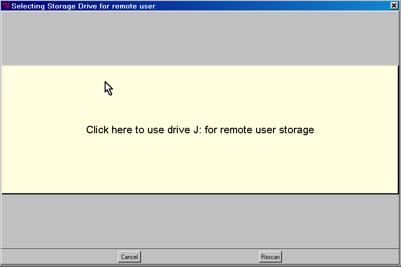
Some checks are made on the flash drive. If it was previously a remote flash drive, the following prompt is given:
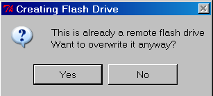
If “Yes” is selected, a check will be made for enough room (at least 30 MB). If not, the process will make the client select another flash drive:
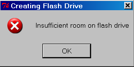
When the flash is done writing:
There are some special startup options that can be used only at the time that EEGer is started. They were originally intended as debugging options but have shown some utility for other uses. The user-available options are listed below.
To use these options, they must be manually added to the startup shortcuts on the desktop. To do this:
RIGHT-click on the EEGer startup option on the desktop
LEFT-click on the properties item on the popup menu
Click on the Shortcut tab
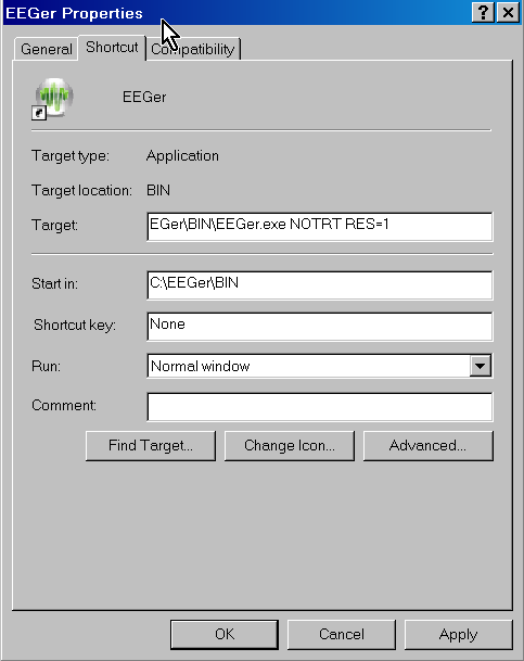
Add the desired options to the
END of the target line, making sure to leave space(s) between each
item.
Click on OK
Now whenever EEGer is started using that shortcut, the applicable options will be used. It is possible to have several shortcuts with different options (as long as you name them so you can remember what they are).
WARNING: REINSTALLING EEGER DOES NOT ERASE ANY OPTIONS MANUALLY SET IN THE SHORTCUT!!!
Available options:
RES=1
RES=2
These options force the EEGer (or EGS) screen size to be either 800x600 (RES=1) or 1024x768 (RES=2) no matter what size the screen graphics resolution is set for. Normally (or any other RES values), EEGer (and EGS) size themselves to the current screen resolution(s).
NOTRT
This option forces EEGer to NOT set realtime priorities. Some machines may function adequately with this option set but some may not. Your mileage may vary.
FORCEREMOTE
This option forces EEGer into being a remote user no matter what the license/dongle may be set for. It is intended for testing remote operations but may be used by a clinician for training clients to use the remote menus.
NOREMINDER
This option turn off the yellow reminder messages that appear at the bottom of the status window (LOST KEYBOARD, NOT RUNNING, etc.). Used normally by people smarter than EEGer and annoyed by the 1-second flashing messages.
NOOVERRUN
EEGer no longer aborts on graphics overruns and does not put up those annoying messages. This option turns the messages back on but EEGer still does not abort on graphics overruns (it just runs slower).
NOFREEZE
This option tells EEGer to NOT lock the position of the EEGer windows but allows them to be dragged around. Note that you cannot drag the realtime graphics screens since there is no border.
NOFOREGROUND
This option tells EEGer not to try forcing itself as the foreground window (so it can get keystrokes).
This program was provided as an aid to technical support. It displays certain crucial pieces of information and provides shortcuts to the various Windows programs needed to resolve issues.
From the therapist screen, it can be started from the Help menu (Help->Run tech support menu).
From either the therapist screen or the EGS game list screen, it can be started using Alt-T (hold down the Alt button and press the T key momentarily). EEGer or EGS will minimize itself and show the following screen:
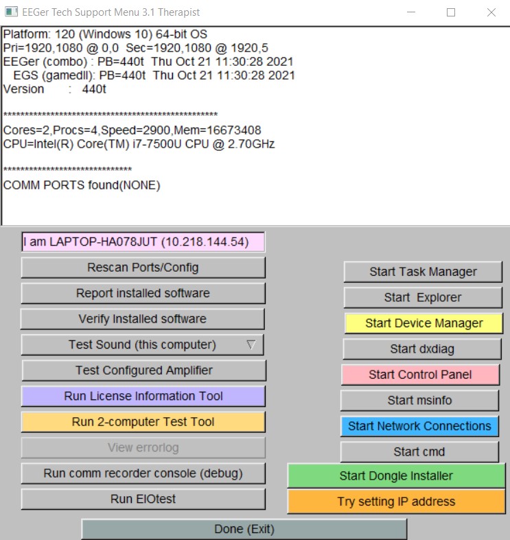
Besides reporting software versions, it also reports the current serial ports (below the line starting with COMM PORTS FOUND) and the current computer name and IP address. The buttons start various programs (when instructed to by Technical Support). The Rescan serial ports button rebuilds the information contained in the recessed display areas in case the attached serial ports or computer IP address have changed. The “Try setting IP address” brings up a window allowing semi-automatic setting of the ethernet addresses.
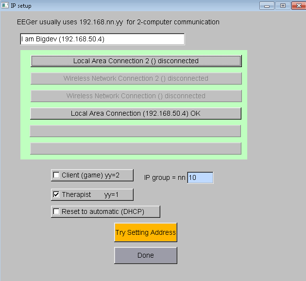
Clicking on the Done button
closes the SetIP page.
Clicking on the Done button of the EEGer Tech Menu closes the program and restarts EEGer or EGS.
EEGer supports a double-blind study mode with the Study Manager feature. In this mode, selected clients are fed prerecorded data from files rather than using the client live signal data. All other actions and controls are the same as using live data and the technician controlling the feedback cannot differentiate between live and simulated data.
How this works is summarized here:
The manager for the study selects previously-recorded (by EEGer) raw data files (or parts of files) using the password-protected Study Manager interface. These files are specified for the three EEGer classes (SMR, EXP, AT). A pool of 10 to 20 files needs to be selected so data “repeat” is minimized.
The manager designates already-existing clients as “simulated data subjects”. At that time, a list of data files is created to be used during simulated sessions. The files can be pre-ordered or randomly ordered.
When a simulated study client session is started (BEGIN SESSION), the next prerecorded file is selected as the “input”.
EEGer monitors the actual live data during the session.
If the amplifier is not operating correctly, the file signal is set to zero.
If the live data from each channel is less than the threshold (currently set at TBD), the corresponding file channel signal is set to zero (as if the electrode is unconnected or has fallen off).
If the live data from the channel is greater than the live threshold, the file signal value is multiplied by a value determined by computing how much the live signal exceeds its average value, triggering an artifact condition. The live signal is never seen.
The actual live data is recorded in a hidden client file.
The data from the session (from the prerecorded
file) is saved as though it was a live session (both raw and
summary data).
There is no visible indication before, during, or after a session
that the study subject IS a study subject (except that the
“results” may differ from actual live feedback).
Caveats:
An experienced clinician may be able to recognize that the feedback doesn't seem to be having a “normal” affect on brain activity. However, the goal of the study logic was to “fool” a technician and not a clinician.
The artifact adjustments made by the technician will not exactly match the live data characteristics so the seeming-artifact file data waveshapes may not exactly match what a live artifact waveshape would be. However, the short-term averages should correspond and correctly drive the artifact controls (which inhibit rewards).
It is the study manager's job to select “suitable” playback files for the pool of files. This must be done BEFORE any clients are selected as “study subjects” (the ordered file list is predefined at selection time). If including 2-channel training for any of the study subjects, it is recommended that ONLY 2-channel recordings be used for control data.
A study subject has ALL three protocol classes in simulated state. You cannot have live data in one class and simulated data in another. Be observant in case the simulated feedback leaves a client in a “bad” state.
An experienced computer user could browse around and find the “hidden” client storage folders but would only be able to correlate a client “ID” by further browsing inside some files.
Access to the study logic is password controlled (so you can't accidentally set this state on someone).
These instructions provide directions to activate and utilize the Study Manager in EEGer.
For Study Manager to function in EEGer, the following items must be valid:
A valid EEGer license for Study Manager must be installed.
EEGer4 4.3 or later must be installed.
To Install the EEGer Keyblock File with the Study Manager option:
Insert the EEGer Keyblock File CD in your CD/DVD drive.
If the contents of the CD are displayed automatically, close the window. You must load the key using EEGer.
Start the EEGer program. From the Files menu, select Read EEGer Keyblock Files.
Select the CD/DVD drive for the Look In field.
The updated keyfile is displayed on the Open dialog. Click the filename to select/highlight and click Open.
Use Review/Replay/Spectral to choose recorded EEG sessions from your existing clients to use for the control sample(s). (10 to 20 control files are recommended)
To access the Study Manager from the main EEGer display, press Ctrl + Alt + Right-Mouse Button at the same time and the Debug menu becomes visible (or not visible if already visible).
From the Debug menu, select Study Manager.
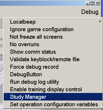
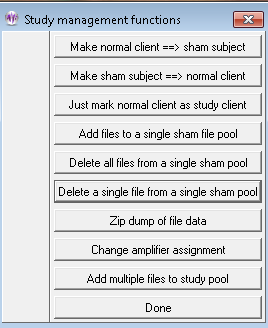
Enter the Password provided to access the Study Manager dialog.
SET UP CONTROL SAMPLE FILES
To set up control data samples, select Add files to a single sham file pool.
Select the desired sham study pool folder:
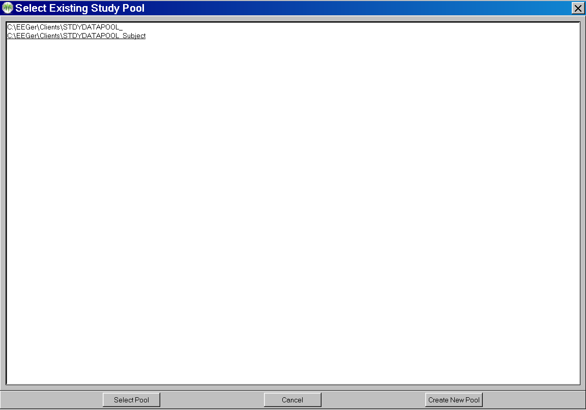
If desired, a new study pool can be created. Clicking on “Create New Pool” brings up a box where the new pool 'name' can be entered.
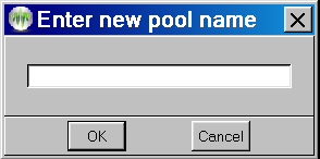
Select Client IDs that contain the desired samples (double-click or click once to highlight and click OK).
Select the desired session(s) from the client’s data (Entire or Partial).
Repeat steps until you have selected the sample set.
SELECT STUDY CLIENTS
Click Make a normal client ==> study subject.
Select the Client ID to convert to a study subject (double-click the ID or click once to highlight and click OK).
Select the desired sham study pool folder.
NOTE: Changing a client to a study subject converts ALL protocol classes for the Client ID to use study control samples.
Choose whether to randomize the order that the study pool files are used or leave them in the order specified by their 'name' (sequential within a particular pool).
Repeat steps 1-3 to
select all study participants.
RESTORECLIENT TO LIVE STATUS
Click Make sham subject ==> normal client
Select the Client ID to convert (double-click the ID or click once to highlight and click OK).
Repeat for each client.
JUST MARK NORMAL CLIENT AS STUDY CLIENT
Click Just mark normal client as study client
Select the Client ID to mark (double-click the ID or click once to highlight and click OK).
Repeat for each desired client. This just marks a client as part of a study for later grouping when exporting study-related data.
DELETE ALL FILES
Click Delete all files from a single sham pool
Select the desired sham study pool folder.
Confirm the deletion.
DELETE A SINGLE FILE
Click Delete a single file from a single sham pool
Select the desired sham study pool folder.
Select the filename to be deleted.
Repeat as desired.
Note: Take great care in deleting files that
may still be selected by a sham
subject.
ZIP DUMP OF FILE DATA
This option allows creating a zip file with client data INCLUDING hidden folders. Do NOT use this if trying to maintain blindness in a study since the hidden files are directly visible. There is a separate utility that can dump data and maintain blindness that should be used by blinded participants.
CHANGE AMPLIFIER ASSIGNMENT
This option allows automatic selection of an amplifier to be used for a study participant.
ADD MULTIPLE FILES TO STUDY POOL
This option is like the Add File option but allows multiple files to be selected at one time.
Some options available to the study manager:
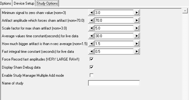
The study manager can specify the lowest average voltage for a signal to “be there” (currently 3 microvolts Peak-Peak). This is usually dependent on the desired electrode placements (and the expected typical readings there).
The study manager can set an absolute amplitude at which an “artifact” condition will be detected. Default value is 70 microvolts peak.
The study manager can determine the scaling of the sham signal when in full artifact (default is 5 times the sham signal). This makes the artifact look “real”.
The study manager can set the time constant for measuring the average Peak-Peak amplitude of the live signal. This is usually 30 seconds (using a moving window).
The study manager can determine the scale factor for NON-max artifacts. The data looks 'real' with a nominal scalar of 1.5 times the live signal average value.
The study manager can specify the fast integral time constant. This controls how fast EEGer tracks the live artifact and how sharp the edges of the artifact are.
The study manager can force recording of fast amplitude data independent of the user selection on the Special option configuration tab.
The study manager can enable certain debug options for sham studies but actual display of values requires an additional command-line option to fully enabled the debug mode.
The study manager can specify the “NAME” of a study for display of a selected study client.
Problems sometimes arise on working systems for no apparent reason. This appendix is a list of some common issues and corrective actions. As always, please contact Technical Support if you are unable to correct the problem.
Dongle not found message on EEGer main screen
This message means that EEGer cannot locate the EEGer dongle (the bright green one). This typically happens if the dongle is plugged in before the software is installed or if a computer goes into “hibernation” (like closing the lid on a laptop) and the power recovery logic of the computer doesn't refresh the USB devices correctly.
Fix:
First, try unplugging the dongle, waiting for 5 or 10 seconds, then plugging it in.
Note: EEGer ONLY looks for the dongle when
starting so you must exit EEGer and then start it again to see if
this fixed things.
Second, you need to UNinstall the driver so Windoze can reinstall it.
To do this, click on “Help->Run tech support menu “and click on the bottom right button labeled “Start Dongle Installer”. UNPLUG the dongle. Check the “Uninstall” option on the lower left of the installation window, then click the button now labeled “Begin Uninstall”. When it finishes, click on the “Start Dongle Installer” button again. This time check the boxes labeled “USB Dongle” and “Standalone”, then click on “Begin Install”. At the completion of the reinstall, you can close various windows (the installer and the Tech Support Menu) and verify that EEGer can detect the dongle (and display the dongle number on the lower left of the main screen).
License Expired:
For a number of reasons, an EEGer clinical user may end up with a keyfile that is expired. If you are on a monthly subscription, you should receive a new keyfile at the beginning of the month that will renew your license till the next month. If this is not installed, or if an older keyfile was installed afterwards, you will get a message saying License Expired. Please make sure your latest keyfile is installed.
There is also a yearly renewal that most EEGer licenses need to function. This message will be proceeded with a warning to contact the Store for an update, but if you have not used your EEGer system for a few months, you might miss the prompt.
License not installed on EEGer main screen
This message means that the EEGer dongle number does not match an installed license file (or that no license file at all is found). Clicking on “Help->Keyfile Information” will display a list of all the license files found on the machine.
Fix:
Install the license file matching the installed dongle using “Files->Read EEGer keyblock files”. The license file is usually emailed but may also be delivered in a download.
If you cannot locate your license files, please contact Customer Support or Technical Support for another copy.
Games not tailored on EEGer main screen
This message means no valid game configuration files are found. EEGer does not “know” what games are physically installed on a computer until the Game Initialization Tool program has an opportunity to scan the computer for them.
Fix:
For single computer systems, run “Tools->Game Initialization Tool”.
For two-computer systems:
On the game computer, run the Game Initialization Tool.
On the therapist computer, run “Tools->Retrieve installed games”
Game Communication Failure
This message means that the therapist computer cannot communicate with the game computer.
Usually, this means an invalid serial port (if using serial interfaces) or invalid/mismatched ethernet addresses (if using ethernet mode). The “ENET” or “COMx” legend on the EGS game screen displays in RED if there is no connections seen and in white if connected and communicating.
Fix:
Serial connection:
The correct serial port must be found on both ends of the connection. On the EGS (game) end, pressing F3 will cycle through all the known serial connections (and ENET). If one of them displays in white, that is a valid connection. Please remember the original value since it may be the OTHER end that is the issue. Normally, when the EEGer program is started on the therapist end, a check is made for valid serial port numbers. If you got that message, please determine the installed ports. This is most easily done by using “Help->Run tech support menu” from the EEGer main screen. The installed ports should be displayed in the recessed message area at the top of the tech support menu. If none are reported, click the button labeled “Start Device Manager”. When the Device manager starts, see if any devices are in yellow (error condition) and/or which ports are shown in the “Ports, COM and LPT” section. If may be that either a USB to serial adapter is not plugged in or that a driver needs reinstallation. Drivers for all devices sold with previous EEGer systems can be found at support.eeger.combut drivers for user-supplied devices have to be located. Once a port is located, the configuration must be set in “Options->EEGer configuration Options” on the “Devices” tab in the field labeled “Serial port for game computer connection”.
Ethernet connection:
The most common issue here is having a wireless connection AND a wired connection. It seems that Windows has its own priority for ethernet addresses and “assumes” the device to use. Unfortunately, the default fixed address usually used by EEGer (192.168.1.*) is also the default address range used by most wireless routers. One thing to try is to make the EEGer game/therapist fixed addresses by in the 192.168.9.* range (192.168.9.1 for therapist/192.168.9.2 for game). Please contact Technical Support for problems since there are too many possibilities to cover each one in this appendix.
Game never shows up on menus even after installing keyfile
Installing a game keyfile does NOT install the game itself.
Fix:
Install the game. Games can be downloaded from the support site (support.eeger.com).
Game shows as pink in Game Selection
If the game shows a button in pink, it means that there is NOT a license for that game installed on the computer. It also means you cannot use the game from the Begin Session button.
Fix:
Please contact Customer Support for the game license.
Same data shows on both screens
This commonly happens on Dual-monitor laptops when the laptop is started/resumed and the external monitor is NOT plugged in.
Fix:
Close EEGer. RIGHT-click on an empty part of the Windows desktop and select “Screen resolution”. Make sure you see two monitors listed. Change the line labeled “Multiple displays” to say “Extend these displays” and click “Apply”.
To avoid having to do this all the time, make sure the monitor is plugged in before starting/resuming the laptop.
Errors when reading remote-use updates
These errors mean there is a process problem with using the updates. Common errors include:
7 This means the update file was ALREADY used.
100 This means the EEGer dongle number doesn't match the number in the update file
143,101 This means the client ID doesn't match
2,102 This means a date error (expired or invalid)
There are many other error codes.
Fix:
Usually, another update file from the supervising clinician will resolve the problem.
Otherwise, please contact Technical Support for assistance.
Realtime overruns
This message (or messages) that abort a session usually indicate some other program is using too much computer time and interfering with the timely processing of feedback data. Usually, this is some kind of antivirus (like Kaspersky).
Fix:
Make sure no other programs are running when EEGer is running.
You CAN disable this error process if you are sure the data is being properly processed by using the settings on the “Special” tab of the EEGer configuration options.
DVD game display is on therapist monitor
The DVD image is either black or on the therapist screen instead of the game screen.
Fix:
Exit EEGer. Start VLC by itself. Drag the menu bar to be completely on the game monitor. Close VLC. This is because VLC “remembers” the screen it was last on when it starts up.
Or, install a version of DVDGame from version 1.19 or later. These versions force the video to the second screen if it is not already there.
“No REMLock Found” Home Use error Message
Neurofeedback is a powerful training modality that can have undesired results if used incorrectly. Because of this, Home Use with EEGer requires a supervising clinician to specify the number of sessions and type of training allowed by a home use client.
To prevent misuse, protections are built into the software. These protections keep home use files from being installed multiple times, or installed on multiple computers. This ensures that a home-user is only able to run sessions permitted by their supervising clinician. If the possibility for misuse is detected, the dongle will be ‘locked’ to prevent unauthorized training.
As a consequence of this, there are certain situations where this can occur without misuse intended. The most common cause of this message is a home-use license moving to a new computer. This can happen if a home-user has to change or upgrade computers, but also if a dongle is returned to a clinician and subsequently rented to a new home-user for use on their own personal computer.
In these cases, the supervising clinician will need to contact EEG Store to ‘unlock’ the dongle. A special keyfile will be sent and, once installed onto the home-use system, will correct the issue. To request this keyfile, the supervising clinician can contact EEG Store by email.
Please be sure to provide the home-use dongle number, clinical dongle number, and a brief description of the situation/events that caused the message to appear. Once the information is verified, an enabling keyfile will be sent to the supervising clinician to provide their home-user.
Note that devices whose status is NOT “Currently supported” are not selectable for use unless the user explicitly enables them for use. In these modes, the device is not approved for anything but investigational use under the health care professional's license conditions.
|
Device Name |
Manufacturer |
Hardware Interface |
Interface method |
Support status |
EEG Channels Supported |
P/F |
|---|---|---|---|---|---|---|
|
BrainLynx |
J&J Engineering |
USB |
Mfr DLL |
Currently supported |
2 |
P |
|
C2mini |
J&J Engineering |
USB |
Mfr DLL |
Obsolete/ supported |
2 |
U |
|
C2 |
J&J Engineering |
USB |
Mfr DLL |
Obsolete/ supported |
2 |
U |
|
C2+mini |
J&J Engineering |
USB |
Mfr DLL |
Currently supported |
2 |
P |
|
C2+ |
J&J Engineering |
USB |
Mfr DLL |
Currently supported |
2 |
P |
|
Spectrum 2 |
J&J Engineering |
USB |
Mfr DLL |
Currently supported |
2 |
P |
|
Spectrum 4 |
J&J Engineering |
USB |
Mfr DLL |
Currently supported |
2/4 |
P |
|
NeruoAmp |
BeeMedic Technology |
USB |
Mfr DLL |
Currently Supported |
2 |
P |
|
esiPro 2.2 |
TeleDiagnostic Systems |
USB |
Mfr DLL |
Currently supported |
2 |
P |
|
esiPro 4.3 |
TeleDiagnostic Systems |
USB |
Mfr DLL |
Currently supported |
2/4 |
P |
|
A200 |
Phoenix Neuro Systems |
USB |
Mfr DLL |
Currently supported |
2 |
P |
|
A400 |
Phoenix Neuro Systems |
USB |
Mfr DLL |
Currently supported |
2/4 |
P |
|
|
|
|
|
|
|
|
|
ProComp2 |
Thought Technology |
Serial port |
Internal code |
Currently supported |
2 |
P |
|
ProComp+ |
Thought Technology |
Serial port |
Internal code |
Currently supported |
2 |
P |
|
Infiniti |
Thought Technology |
Serial port |
Internal code |
Currently supported |
2 |
P |
|
ProComp2 |
Thought Technology |
USB |
Mfr DLL |
Currently supported |
2 |
P |
|
ProComp+ |
Thought Technology |
USB |
Mfr DLL |
Currently supported |
2/4 |
P |
|
Infiniti |
Thought Technology |
USB |
Mfr DLL |
Currently supported |
2/4 |
P |
|
ProComp5 |
Thought Technology |
USB |
Mfr DLL |
Currently supported |
2/4 |
P |
|
|
|
|
|
|
|
|
|
Brainmaster 2E |
Brainmaster |
Serial port |
Mfr DLL |
Currently supported |
2 |
P |
|
Atlantis 2 |
Brainmaster |
USB with serial port |
Mfr DLL |
Currently supported |
2 |
P |
|
Atlantis 4 |
Brainmaster |
USB with serial port |
Mfr DLL |
Currently supported |
2/4 |
P |
|
Discovery |
Brainmaster |
USB with serial port |
Mfr DLL |
Currently supported |
2/4 of 24 |
U |
|
|
|
|
|
|
|
|
|
Pet2.0 |
Brainquiry |
Bluetooth serial |
Internal code |
Obsolete/no device but previously supported |
2 |
U |
|
QPET |
Brainquiry |
Bluetooth serial |
Mfr DLL |
Obsolete/no device but previously supported |
2 |
U |
|
Pendant-EEG |
Pocket-Neurobics |
Bluetooth serial |
Internal code |
Under test/no device but previously supported |
2 |
U |
|
Q-Wiz |
Pocket-Neurobics |
USB or Bluetooth serial |
Internal code |
Experimental-currently supported |
2/4 |
P |
|
U-Wiz |
Pocket-Neurobics |
USB or Bluetooth serial |
Internal code |
Experimental-currently supported |
2 |
P |
|
(external amplifier) |
------------------ |
USB |
A/D device supported by Measurement Computing Corporation InstaCal software |
Currently supported (used for system testing) |
2/4 |
P |
|
Q20 |
Neurofield |
PCAN/USB |
PCAN USB library+internal code |
Currently supported |
2/4 of 19 |
P |
|
eVox |
|
Bluetooth serial |
Mfr DLL |
Currently supported |
2/4 of 19 |
P |
|
QDSI |
|
Bluetooth serial |
Mfr DLL |
Experimental-currently supported |
2/4 of 24 |
P |
|
CQuick |
|
Bluetooth serial |
Mfr DLL |
Experimental-currently supported |
2/4 of 19 |
P |
|
MUSE |
|
Bluetooth serial |
Internal code |
Experimental-currently supported |
2/4 |
P |
|
Optima |
Neurobit Systems |
USB or Bluetooth |
Mfr DLL |
Experimental-currently supported |
2/4 |
P |
Clinician Login function on a home-use system enables you(the clinician) to take control of the Home-use system and grants functions that are restricted to clinical system. While Clinician login in active, you can make changes to the session plan such as changing layouts, adjusting frequencies, changing feedback mode, adding stages and so on.
Clinician Login can be enabled on a Home-use client while creating an EKC/EKR on a clinical system by entering the password. If you do not enter any password on the “Clinician Login Password” field while creating EKC/EKR then, you disable Clinician Login in the Home-use system.
When this EKC is installed on a Home-use system, (refer to Create Home-use Client (EKC)), a Home-user can follow session plan initialized during installation. Furthermore, if you (clinician) create Home-use client file without any session permission/limitations, Home-user can only run sessions on that home-use client without any ability to change session plan.
Clinicians can take a hands-on approach and remotely login (refer to https://www.youtube.com/watch?v=hQrJ8_HE28w) to Home-use system to take control of the session. By Navigating to “Client>enable/disable Clinician login” on the main EEGer screen and entering login password for that client (home-use client installed by EKC), you (clinician) can change session plan, adjust frequencies and reward.
Furthermore, you (clinician) can also reduce limitations (or add session permission options) by creating an EKR for the home-user. Please refer to Renew home-use session plan(EKR) to enable permissions to make changes to session plan, frequencies and rewards, and feedback modes.
Please note that Clinician Login when activated only grants clinical system privileges for the selected home-use client. Clinician Login works for only for the Home-use client selected while activating it.
Furthermore, for advanced users, multiple home-use clients with multiple Clinician Login passwords can be installed on the same home-use system. Every time when you switch Home-use client, the active Clinician Login is disabled before logging in with a new home-use client
Error codes:
|
Error Code |
Description |
Reason |
Solution |
|
11 |
Enter dongle number |
Dongle number field is empty |
Enter proper dongle number |
|
12 |
Enter Valid Dongle Number |
Wrong format or unknown dongle number entered |
Verify if the dongle number entered is correct |
|
13 |
Please enter a valid Home-use dongle number in the 'Dongle Number' field. This is your clinical dongle number |
Clinicians dongle was entered instead of Home-user’s dongle number in the dongle number field |
Verify whether the dongle number entered belongs to the home-user |
|
14 |
Enter valid file description |
File Description filed is empty |
Enter some text as a file description |
|
15 |
The file description cannot have symbols or spaces other than '-' or '_' |
Unsupported symbols in File description field |
Remove any symbols other than ‘-’ and ‘_’ |
|
16 |
The description associated to the file is too big. Description must be less than 60 characters |
File description has more than 60 characters |
Reduce the number of characters used as file description |
|
20 |
You have selected a file format not supported by the utility Only EKC, EKR, ELP and ELS file extensions are supported |
The file which was selected not one of the supported format or not a HU-file |
Verify whether the selected file was created by EEGer or any of its utilities |
|
30 |
Unable to upload file. Check your internet connection or restart the utility |
Something went wrong while connecting to the server/cloud |
Try reconnecting to the internet |
|
31 |
server could not be connected |
Something went wrong while connecting to the server/cloud |
Try reconnecting to the internet |
|
32 |
This tag and dongle prefix already exists on cloud Please change your tag to upload again |
There is already a file which was uploaded by you with the same file description. |
Try using another description. You can add a number or a date code to help you identify |
|
33 |
File upload aborted: Home-use dongle number entered do not match the data in the EKR/EKC file |
The dongle number in the filed does not match the dongle number recorded/saved data in the HU-file. |
Verify if the EKC/EKR was created using the same home-use dongle number |
|
41 |
Enter dongle number |
Dongle number field is empty |
Enter proper dongle number |
|
42 |
Enter Valid Dongle Number |
Wrong format or unknown dongle number entered |
Verify if the dongle number entered is correct |
|
43 |
Please enter a valid Home-use dongle number in the 'Dongle Number' field. This is your clinical dongle number |
Clinicians dongle was entered instead of Home-user’s dongle number in the dongle number field |
Verify whether the dongle number entered belongs to the home-user |
|
44 |
No Files present in the server with this dongle number |
Either the file you are searching was never uploaded or you may have deleted it. |
You can either uploading the files for the home-use dongle number again or verify if you have entered the correct dongle number |
|
50 |
Cannot connect to the server |
Something went wrong while connecting to the server/cloud |
Try reconnecting to the internet |
Note: The clinician will discover a file named remotedonglenumber_yymmddhhmm.EKR or remotedonglenumber_yymmddhhmm.EKC (where remotedonglenumberis the user's dongle number and the yy...number makes for uniqueness) on the clinician’s computer. The filename thus does NOT contain any client-identifying data although the internal contents of the “.EKC” and “.EKR” file does (client name and birthdate). Please observe HIPAA rules. This file is designed to be transferable over email or by the HU-utility. Also these filesare onlyread and verified by EEGer.
|
Error Code |
Description |
Reason |
Solution |
|
1.0 |
Could not connect to the server + reason |
Either internet connection is bad or server is down/channel is closed |
Try reconnecting to the internet or if it says channel is closed, wait for sometime (20-30 mins) and try running the utility |
|
2.0 |
File cannot be uploaded |
Somehow there is already an EKX with the same name and cannot be overwritten |
Contact tech support |
|
2.1 |
File cannot be uploaded |
Older file with same was removed but new one had issues while uploading |
Contact tech support |
|
3.0 |
Failed to process EKX in the server + reason |
Somehow the EKX generated by EEGer was either corrupted or empty |
Check if you have a working dongle. Make sure internet connection is not intermittent |
|
3.2 |
Error in processing EKX + reason |
Some run time error while processing EKX in the server |
Contact tech support |
|
3.3 |
Failed to download EKB |
Any other error that was not handled by the server |
Contact tech support |
Clicking on the Spectral display of a Sessionundertoolsbutton brings up a raw file selection screen.
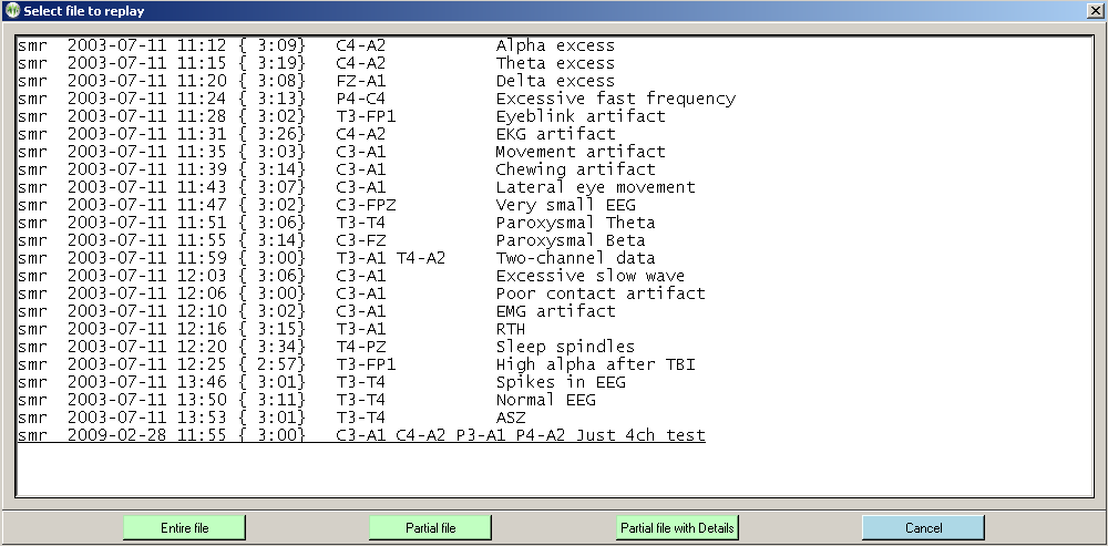
Once the file is selected, the graphical display of the data is begun. A typical screen looks like this:
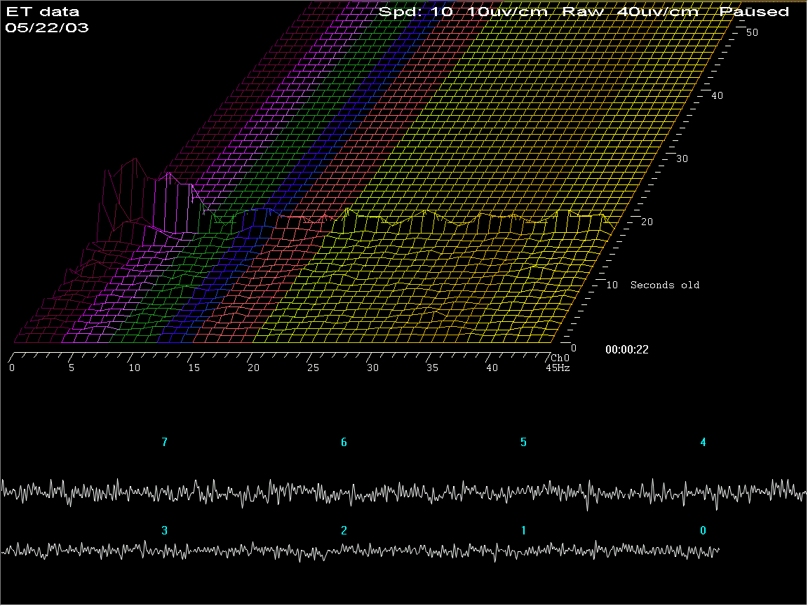
The top part of the screen shows spectral (FFT) data as a three-dimensional plot of frequency (horizontal), time (perspective), and amplitude (vertical). The coloration of the frequency bands uses the customizable color scheme used throughout EEGer. The bottom part of the screen shows the raw signal corresponding to the spectral data. The legends on the raw data show how many seconds “old” the raw data is. The “newest” raw data corresponds to the front-most spectral display row.
This is the screen with the time axis shown vertically (by moving the viewing angle left) and the dominant frequency marker turned on. Notice the 10-second average dominant frequency value shown to the immediate right of the channel assignment value.
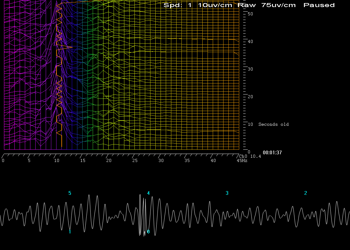
Pressing F1 brings up a help menu showing the key options available.
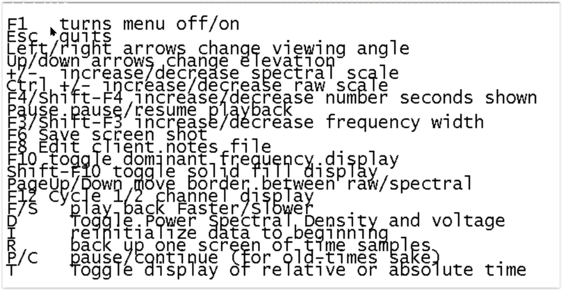
|
F1 |
toggles the help screen off/on. |
|
Esc |
terminates the spectral replay and returns to the top menu. |
|
left/right arrows |
change the viewing angle by moving the apparent vanishing point left/right. |
|
up/down arrows |
change the apparent elevation angle by moving the apparent vanishing point up/down. |
|
+/- |
change the relative spectral scale. |
|
Ctrl +/- |
change the relative raw data scale. |
|
F4/Shift-F4 |
increases/decreases the “number of seconds” of data shown (apparent depth of display). |
|
Pause |
pauses/resumes playback of data. |
|
F3/Shift-F3 |
increases/decreases the displayed number of frequency bins. The computation always uses a 1 Hz bandwidth but the clinician may only be interested in the lower 10 Hz. |
|
F6 |
saves a screen for later printing. Black and white are reversed in the print file. |
|
F8 |
Raise/lower the editor screen |
|
F10 |
Toggles display of dominant frequency line (which uses color 49 of the current color set). |
|
Shift-F10 |
Toggles display of solid fill for colors |
|
Page-Up/ Page-Down |
moves the border between the raw and spectral data. |
|
F12 |
changes the display between two-channel/channel A only/channel B only modes. |
|
F/S |
make the playback be faster/slower than real time. |
|
I |
pauses playback and rewinds the data point back to the beginning. |
|
R |
pauses playback and backs up one “number of seconds” worth of data. |
|
P |
pauses playback. |
|
C |
continues playback from a pause. |
|
D |
Toggles between voltage amplitude on spectral display and Power Spectral Density display (voltage squared). PSD tends to show changes more dramatically. |
|
T |
Toggle time display between time-of-day and relative time in session. |
This is what a two-channel screen display looks like (after pressing F12 several times).
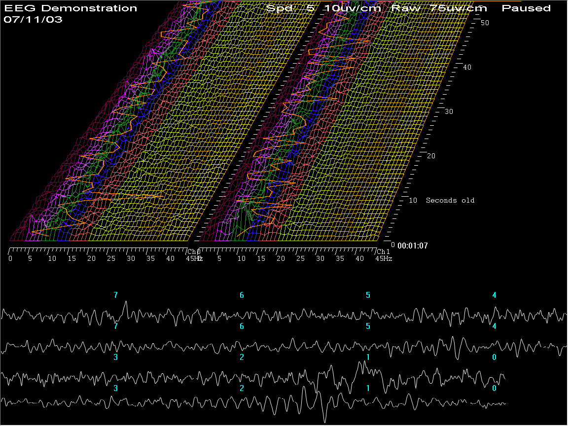
Note that the dominant frequency display marker is turned on (using
F10).
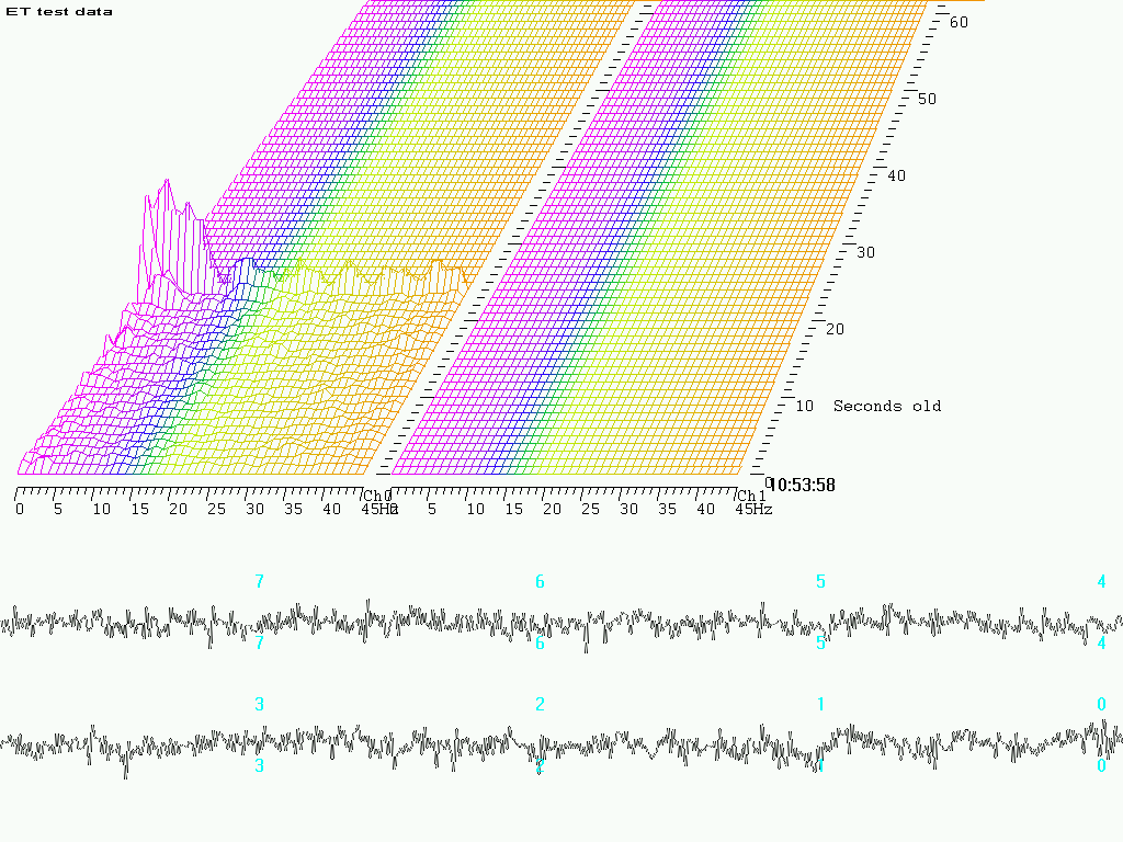
Pressing F6 causes a printout to be saved with black and white
reversed (to save printer ink).